The biosynthetic pathways leading to amino acids and nucleotides share a requirement for nitrogen. Soluble, biologically useful nitrogen compounds are generally scarce in natural environments; thus, most organisms use ammonia, amino acids, and nucleotides economically. Available amino acids, purines, and pyrimidines formed during metabolic turnover of proteins and nucleic acids are often salvaged and reused. We begin by examining the pathways by which nitrogen from the environment is introduced into biological systems.
A Global Nitrogen Cycling Network Maintains a Pool of Biologically Available Nitrogen
The movement of nitrogen through the biosphere has been viewed historically as a cycle. However, our evolving understanding of the complexity of nitrogenous interconversions makes it clear that nitrogen moves through a complex web, rather than in a neat cycle (Fig. 22-1). Earth’s atmosphere is four-fifths molecular nitrogen . However, is too unreactive to be of use to living organisms. Conversion of to forms that can support life is called nitrogen fixation. The reduction of to plays such a central role in making available that this one reaction is often considered synonymous with nitrogen fixation. In the biosphere, the metabolic processes of countless species function interdependently to salvage and reuse biologically available nitrogen. Most of the key reactions are carried out by bacteria and archaea.
FIGURE 22-1 The global nitrogen web. The total amount of nitrogen fixed annually in the biosphere exceeds ; industrial sources of fixed nitrogen are now nearly as great. Reactions are identified with the processes they are involved in by colored arrows (see key). The oxidation number of the N atom is indicated on the vertical axis. [Information from M. M. M. Kuypers et al., Nat. Rev. Microbiol. 16:263, 2018, Fig. 1.]
The reduction of atmospheric nitrogen by nitrogen-fixing bacteria and archaea to yield ammonia , provides a useful anchor for our discussion. This critical process, described in detail in Section 22.2, provides most of the reduced nitrogen for incorporation into biomolecules.
Free ammonia does not build up, and reduction is balanced by oxidation. Bacteria that derive their energy by oxidizing ammonia to nitrite and ultimately nitrate are abundant and active in both terrestrial and marine environments. The processes of converting ammonia to nitric oxide, nitrite, and finally nitrate are known as nitrification (Fig. 22-1, purple arrows). Individual bacterial or archaeal species may promote one or more of these steps.
Atmospheric must be replaced in order to maintain levels at a steady-state concentration. Some of the replacement comes from reduction of nitrate and nitrite. The reduction of nitrate and nitrite to under anaerobic conditions, a process called denitrification (Fig. 22-1, red arrows), is carried out by specialized microorganisms in all three domains of life. These organisms use or rather than as the ultimate electron acceptor in a series of reactions that (like oxidative phosphorylation) generates a transmembrane proton gradient, which is used to synthesize ATP. These microorganisms exist in all anoxic environments where nitrate is present, including soils, marine sediments, and eutrophic marine zones. An alternative path back to atmospheric is provided by a group of bacteria that promote anaerobic ammonia oxidation, or anammox (Fig. 22-1, blue arrows). Anammox converts ammonia and nitrite to . As much as 50% to 70% of the conversion in the biosphere may occur through this pathway, which went undetected until the 1980s. The obligate anaerobes that promote anammox are fascinating in their own right and are providing some useful solutions to waste-treatment problems (Box 22-1).
Fixation of atmospheric is not the only source of reduced ammonia for biological systems. Much of it comes from an alternative fate of nitrate that circumvents denitrification. More than 90% of the generated by vascular plants, algae, and microorganisms comes from nitrate assimilation, a two-step reductive process that bypasses atmospheric . First is reduced to by nitrate reductase, then the is reduced to in a six-electron transfer catalyzed by nitrite reductase (Fig. 22-2). Both reactions involve chains of electron carriers and cofactors we have not yet encountered. Nitrate reductase is a large, soluble protein . Within the enzyme, a pair of electrons, donated by NADH, flows through groups of cysteine, FAD, and a cytochrome , then to a novel cofactor containing molybdenum, before reducing the substrate to .
FIGURE 22-2 Nitrate assimilation by nitrate reductase and nitrite reductase. (a) Nitrate reductases of plants and bacteria catalyze the two-electron reduction of to , in which a novel Mo-containing cofactor plays a central role. NADH is the electron donor. (b) Nitrite reductase converts the product of nitrate reductase into in a six-electron, eight-proton transfer process in which the metallic center in siroheme carries electrons and the carboxyl groups of siroheme may donate protons. The initial source of electrons is reduced ferredoxin.
The nitrite reductase of plants is located in the chloroplasts and receives its electrons from ferredoxin (which is reduced in the light-dependent reactions of photosynthesis; see Section 20.2). Six electrons, donated one at a time by ferredoxin, pass through a 4Fe-4S center in the enzyme, then through a novel hemelike molecule (siroheme) before reducing to (Fig. 22-2). Nonphotosynthetic microbes possess a distinct nitrite reductase for which NADPH is the electron donor.
Human activity presents an increasing challenge to the global nitrogen balance, and to all life in the biosphere supported by that balance. Fixed nitrogen is increasingly necessary to boost production in agriculture. Industrial nitrogen-based fertilizers now contribute as much ammonia and other reactive nitrogen species to the biosphere as do natural processes. Nonfarming manufacturing activity releases additional reactive nitrogen into the atmosphere, including nitric oxide, a prominent greenhouse gas. Controlling the damaging effects of agricultural runoff and industrial pollutants will remain an important component of the continuing effort to expand the food supply for a growing human population.
Nitrogen Is Fixed by Enzymes of the Nitrogenase Complex
The availability of fixed nitrogen, an essential nutrient, may have limited the size of the primordial biosphere. As early cells acquired a capacity to fix atmospheric nitrogen, the biosphere expanded. Evidence for biological nitrogen fixation has been found in sedimentary rocks more than 3 billion years old.
In the biosphere of today, only certain bacteria and archaea can fix atmospheric . These organisms, called diazotrophs, include the cyanobacteria of soils and fresh and salt waters, methanogenic archaea (strict anaerobes that obtain energy and carbon by converting and to methane), other kinds of free-living soil bacteria such as Azotobacter species, and the nitrogen-fixing bacteria that live as symbionts in the root nodules of leguminous plants. The most important product of nitrogen fixation is ammonia, which can be used by all organisms either directly or after its conversion to other soluble compounds such as nitrites, nitrates, or amino acids.
The reduction of nitrogen to ammonia is an exergonic reaction:
The triple bond, however, is very stable, with a bond energy of 930 kJ/mol. Nitrogen fixation therefore has an extremely high activation energy, and atmospheric nitrogen is almost chemically inert under normal conditions. Ammonia is produced industrially by the Haber process (named for its inventor, Fritz Haber), which requires temperatures of 400 to 500 °C and nitrogen and hydrogen at pressures of tens of thousands of kilopascals (several hundred atmospheres) to provide the necessary activation energy.
Biological nitrogen fixation must occur at biological temperatures and at 0.8 atm of nitrogen, and the high activation barrier is overcome by other means. This is accomplished, at least in part, by the binding and hydrolysis of ATP. The overall reaction can be written
Biological nitrogen fixation to produce ammonia is carried out by a highly conserved complex of proteins called the nitrogenase complex; its central components are dinitrogenase reductase and dinitrogenase (Fig. 22-3a). Dinitrogenase reductase is a dimer of two identical subunits. It contains a single 4Fe-4S redox center (see Fig. 19-5), bound between the subunits, and can be oxidized and reduced by one electron. It also has two binding sites for ATP/ADP (one site on each subunit). Dinitrogenase , an tetramer, has two Fe-containing cofactors that transfer electrons (Fig. 22-3b). One, the P cluster, has a pair of 4Fe-4S centers; these share a sulfur atom, making an 8Fe-7S center. The second cofactor in dinitrogenase, the FeMo cofactor, is a novel structure composed of 7 Fe atoms, 9 inorganic S atoms, a Cys side chain, and a single carbon atom in the center of the FeS cluster. Also part of the cofactor is a molybdenum atom, with ligands that include three inorganic S atoms, a His side chain, and two oxygen atoms from a molecule of homocitrate that is an intrinsic part of the FeMo cofactor.
FIGURE 22-3 Enzymes and cofactors of the nitrogenase complex. (a) The holoenzyme consists of two identical dinitrogenase reductase molecules (green), each with a 4Fe-4S redox center and binding sites for two ATP, and two identical dinitrogenase heterodimers (purple and blue), each with a P cluster (Fe-S center) and an FeMo cofactor. In this structure, ADP is bound in the ATP site, to make the crystal more stable. (b) The electron-transfer cofactors. A P cluster is shown here in its reduced (top) and oxidized (middle) forms. The FeMo cofactor (bottom) has a Mo atom with three S ligands, a His ligand, and two oxygen ligands from a molecule of homocitrate. In some organisms, the Mo atom is replaced with a vanadium atom. (Fe is shown in orange, S in yellow.) [Data from (a) PDB ID 1N2C, H. Schindelin et al., Nature 387:370, 1997; (b) : PDB ID 3MIN, and : PDB ID 2MIN, J. W. Peters et al., Biochemistry 36:1181, 1997; FeMo cofactor: PDB ID 1M1N, O. Einsle et al., Science 297:1696, 2002.]
There are two additional forms of nitrogenase. One includes a dinitrogenase with a vanadium-containing cofactor rather than molybdenum (VFe); the other contains a second Fe atom (FeFe). Each of the nitrogenase complexes is encoded by a separate set of genes. The FeMo nitrogenase complex is the ancestral type, and all nitrogen-fixing bacteria and archaea contain it. Some species can produce one or both of the alternative VFe or FeFe types. Although the alternative enzymes are somewhat less efficient, they may play important roles in environments in which molybdenum is limiting or absent. They may also permit some additional reactions to occur. The vanadium nitrogenase system of Azotobacter vinelandii has the remarkable capacity to catalyze the reduction of carbon monoxide (CO) to ethylene , ethane, and propane.
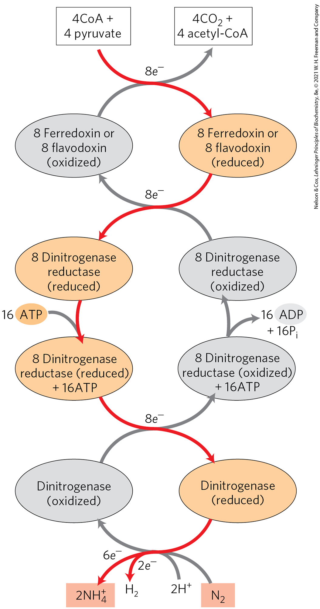
Nitrogen fixation to produce ammonia is carried out by a highly reduced form of dinitrogenase and requires eight electrons: six for the reduction of and two to produce one molecule of . Production of is an obligate part of the reaction mechanism, but the biological role of in the process is not understood.
Dinitrogenase is reduced by the transfer of electrons from dinitrogenase reductase (Fig. 22-4). The dinitrogenase tetramer has two binding sites for the reductase. The required eight electrons are transferred from reductase to dinitrogenase one at a time: a reduced reductase molecule binds to the dinitrogenase and transfers a single electron, then the oxidized reductase dissociates from dinitrogenase, in a repeating cycle. Each turn of the cycle requires the hydrolysis of two ATP molecules by the dimeric reductase. The immediate source of electrons to reduce dinitrogenase reductase varies, with reduced ferredoxin (see Section 20.2), reduced flavodoxin, and perhaps other sources playing a role. In at least one species, the ultimate source of electrons to reduce ferredoxin is pyruvate.
FIGURE 22-4 Electron path in nitrogen fixation by the nitrogenase complex. Electrons are transferred from pyruvate to dinitrogenase via ferredoxin (or flavodoxin) and dinitrogenase reductase. Dinitrogenase reductase reduces dinitrogenase one electron at a time, with at least six electrons required to fix one molecule of . Two additional electrons are used to reduce to in a process that obligatorily accompanies nitrogen fixation in anaerobes, making a total of eight electrons required per molecule. The subunit structures and metal cofactors of the dinitrogenase reductase and dinitrogenase proteins are described in the text and in Figure 22-3.
In the reaction carried out by dinitrogenase reductase, both ATP binding and ATP hydrolysis bring about protein conformational changes that help overcome the high activation energy of nitrogen fixation. The binding of two ATP molecules to the reductase shifts the reduction potential of this protein from to , an enhancement of its reducing power that is required to transfer electrons through dinitrogenase to ; the standard reduction potential for the half-reaction is . The ATP molecules are then hydrolyzed just before the actual transfer of one electron to dinitrogenase.
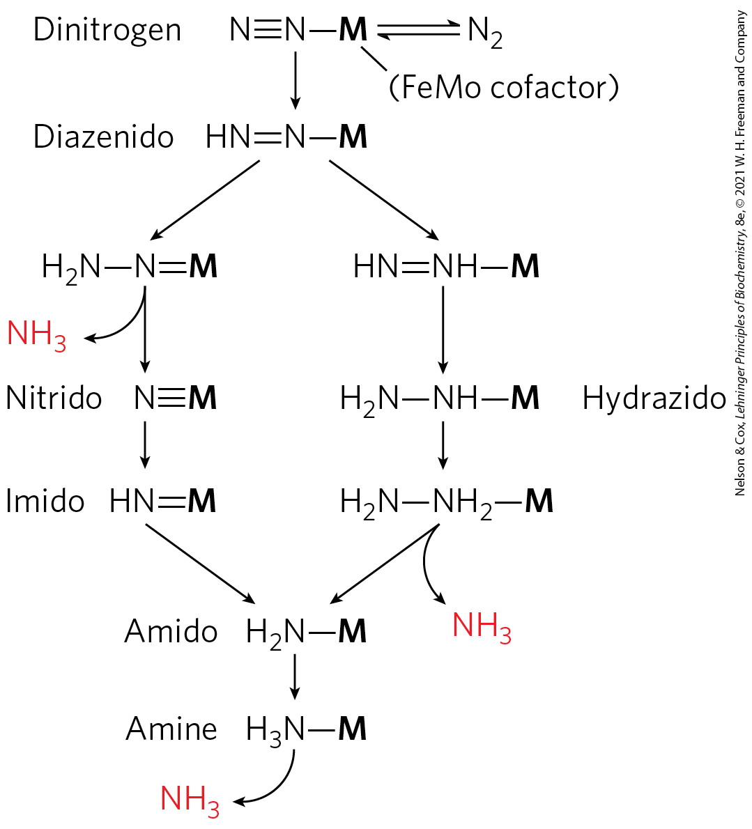
ATP binding and hydrolysis change the conformation of nitrogenase reductase in two regions, which are structurally homologous with the switch 1 and switch 2 regions of the GTP-binding proteins involved in biological signaling (see Fig. 12-12). ATP binding produces a conformational change that brings the 4Fe-4S center of the reductase closer to the P cluster of dinitrogenase (from 18 Å to 14 Å away), which facilitates electron transfer between the reductase and dinitrogenase. The details of electron transfer from the P cluster to the FeMo cofactor, and the means by which eight electrons are accumulated by nitrogenase, are not yet known in detail. Two pathways that conform to available data, both involving the Mo atom as a central player, are illustrated in Figure 22-5.
FIGURE 22-5 Two reasonable hypotheses for the intermediates involved in reduction. In both scenarios, the FeMo cofactor (abbreviated as M here) plays a central role, binding directly to one of the nitrogen atoms of and remaining bound throughout the sequence of reduction steps. [Information from L. C. Seefeldt et al., Annu. Rev. Biochem. 78:701, 2009, Fig. 9.]
The nitrogenase complex is remarkably unstable in the presence of oxygen. The reductase is inactivated in air, with a half-life of 30 seconds; dinitrogenase has a half-life of only 10 minutes in air. Free-living bacteria that fix nitrogen cope with this problem in a variety of ways. Some live only anaerobically or repress nitrogenase synthesis when oxygen is present. Some aerobic species, such as A. vinelandii, partially uncouple electron transfer from ATP synthesis so that oxygen is burned off as rapidly as it enters the cell (see Box 19-1). When fixing nitrogen, cultures of these bacteria increase in temperature as a result of their efforts to rid themselves of oxygen.
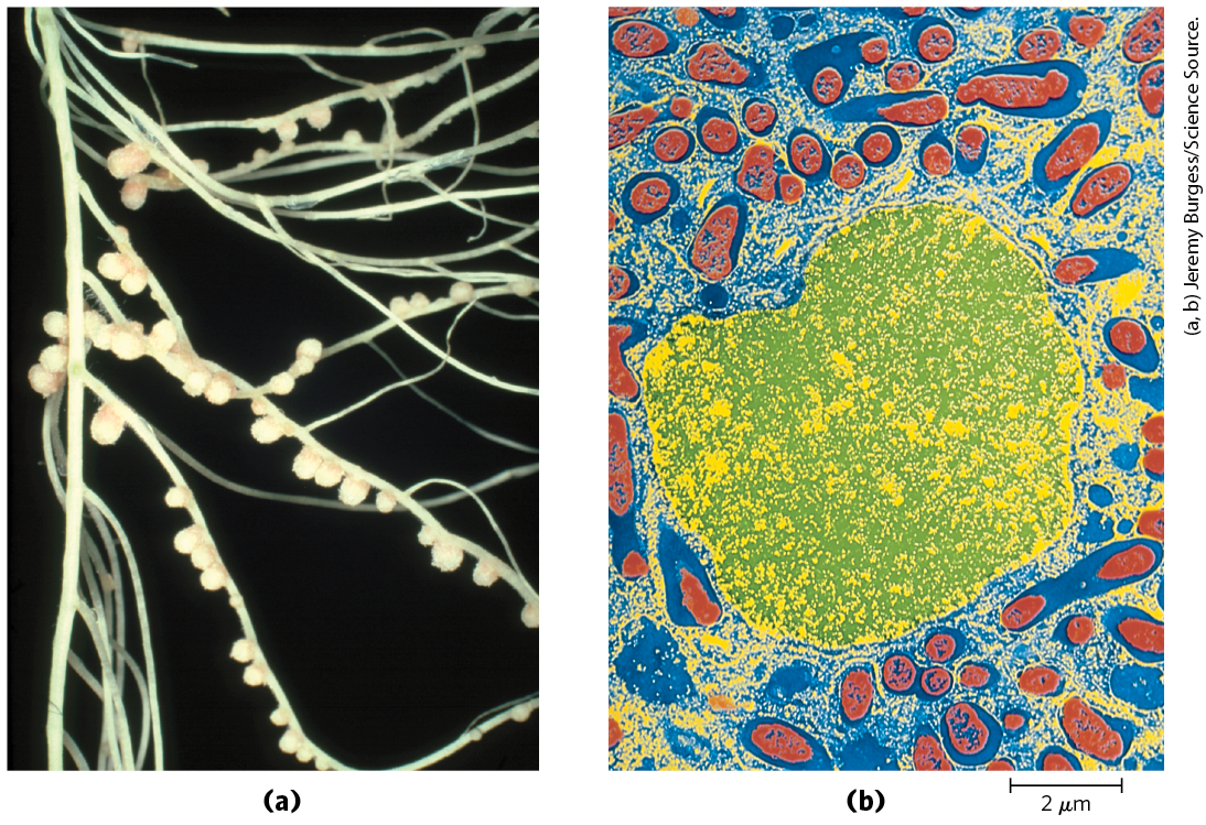
The symbiotic relationship between leguminous plants and the nitrogen-fixing bacteria in their root nodules (Fig. 22-6) takes care of both the energy requirements and the oxygen lability of the nitrogenase complex. The energy required for nitrogen fixation was probably the evolutionary driving force for this plant-bacteria association. The bacteria in root nodules have access to a large reservoir of energy in the form of abundant carbohydrate and citric acid cycle intermediates made available by the plant. This may allow the bacteria to fix hundreds of times more nitrogen than do their free-living cousins under conditions generally encountered in soils. To solve the oxygen-toxicity problem, the bacteria in root nodules are bathed in a solution of the oxygen-binding heme protein leghemoglobin, produced by the plant (although the heme may be contributed by the bacteria). Leghemoglobin binds all available oxygen so that it cannot interfere with nitrogen fixation, and it efficiently delivers the oxygen to the bacterial electron-transfer system. The benefit to the plant, of course, is a ready supply of reduced nitrogen. In fact, the bacterial symbionts typically produce far more than is needed by their symbiotic partner; the excess is released into the soil. The efficiency of the symbiosis between plants and bacteria is evident in the enrichment of soil nitrogen brought about by leguminous plants. This enrichment of in the soil is the basis of crop rotation methods, in which plantings of nonleguminous plants (such as maize) that extract fixed nitrogen from the soil are alternated with plantings of legumes such as alfalfa, peas, or clover.
FIGURE 22-6 Nitrogen-fixing nodules. (a) Pea plant (Pisum sativum) root nodules containing the nitrogen-fixing bacterium Rhizobium leguminosarum. The nodules are pink due to the presence of leghemoglobin; this heme protein has a very high binding affinity for oxygen, which strongly inhibits nitrogenase. (b) Artificially colorized electron micrograph of a thin section through a pea root nodule. Symbiotic nitrogen-fixing bacteria, or bacteroids (red), live inside the nodule cell, surrounded by the peribacteroid membrane (blue). Bacteroids produce the nitrogenase complex that converts atmospheric nitrogen to ammonium ; without the bacteroids, the plant is unable to utilize . (The cell nucleus is shown in yellow/green. Not visible in this micrograph are other organelles of the infected root cell that are normally found in plant cells.)
Nitrogen fixation is energetically costly: 16 ATP and 8 electrons yield only 2 . It is therefore not surprising that the process is tightly regulated so that is produced only when needed. High [ADP], an indicator of low [ATP], is a strong inhibitor of nitrogenase. represses the expression of the ~20 nitrogen fixation (nif) genes, effectively shutting down the pathway. Covalent alteration of nitrogenase is also used in some diazotrophs to control nitrogen fixation in response to the availability of in the surroundings. Transfer of an ADP-ribosyl group from NADH to a specific Arg residue in the nitrogenase reductase shuts down fixation in Rhodospirillum, for example. This is the same covalent modification that we saw in the case of G protein inhibition by the toxins of cholera and pertussis (see Fig. 12-14).
Nitrogen fixation is the subject of intense study because of its immense practical importance. Industrial production of ammonia for use in fertilizers requires a large and expensive input of energy, and this has spurred a drive to develop recombinant or transgenic organisms that can fix nitrogen. In principle, recombinant DNA techniques (Chapter 9) might be used to transfer the DNA that encodes the enzymes of nitrogen fixation into non-nitrogen-fixing bacteria and plants. However, those genes alone will not suffice. About 20 genes are essential to nitrogenase activity in bacteria, many of them needed for the synthesis, assembly, and insertion of the cofactors. There is also the problem of protecting the enzyme in its new setting from destruction by oxygen. In all, there are formidable challenges in engineering new nitrogen-fixing plants. Success in these efforts will depend on overcoming the problem of oxygen toxicity in any cell that produces nitrogenase.
Ammonia Is Incorporated into Biomolecules through Glutamate and Glutamine
Reduced nitrogen in the form of is assimilated into amino acids and then into other nitrogen-containing biomolecules. Two amino acids, glutamate and glutamine, provide the critical entry point. Recall that these same two amino acids play central roles in the catabolism of ammonia and amino groups in amino acid oxidation (Chapter 18). Glutamate is the source of amino groups for most other amino acids, through transamination reactions (the reverse of the reaction shown in Fig. 18-4). The amide nitrogen of glutamine is a source of amino groups in a wide range of biosynthetic processes. In most types of cells, and in extracellular fluids in higher organisms, one or both of these amino acids are present at higher concentrations — sometimes an order of magnitude or more higher — than other amino acids. An Escherichia coli cell requires so much glutamate that this amino acid is one of the primary solutes in the cytosol. Its concentration is regulated not only in response to the cell’s nitrogen requirements but also to maintain an osmotic balance between the cytosol and the external medium.
The biosynthetic pathways to glutamate and glutamine are simple, and all or some of the steps occur in most organisms. The most important pathway for the assimilation of into glutamate requires two reactions. The net effect is to convert glutamate, α-ketoglutarate, and ammonia into two molecules of glutamate.
First, is reacted with glutamate to produce glutamine, using the enzyme glutamine synthetase. This reaction takes place in two steps, with enzyme-bound γ-glutamyl phosphate as an intermediate (see Fig. 18-8):
(22-1)
Glutamine synthetase is found in all organisms. In addition to its importance for assimilation in bacteria, it has a central role in amino acid metabolism in mammals, converting free , which is toxic, to glutamine for transport in the blood (Chapter 18).
In the second reaction needed for assimilation, the glutamine reacts with α-ketoglutarate to generate two molecules of glutamate. In bacteria and plants, this reaction is catalyzed by glutamate synthase. (An alternative name for this enzyme, glutamate:oxoglutarate aminotransferase, yields the acronym GOGAT, by which the enzyme also is known.) α-Ketoglutarate, an intermediate of the citric acid cycle, undergoes reductive amination with glutamine as nitrogen donor:
(22-2)
The net reaction of glutamine synthetase and glutamate synthase (Eqns 22-1 and 22-2) is
Glutamate synthase is not present in animals, which instead maintain high levels of glutamate by processes such as the transamination of α-ketoglutarate during amino acid catabolism. Plants possess a second alternative form of glutamate synthase that uses reduced ferredoxin rather than NADPH as a source of reducing electrons.
Glutamate can also be formed in yet another, albeit minor, pathway: the reaction of α-ketoglutarate and to form glutamate in one step. This is catalyzed by glutamate dehydrogenase, an enzyme present in all organisms. Reducing power is furnished by NADPH:
We encountered this reaction in the catabolism of amino acids (see Fig. 18-7). In eukaryotic cells, glutamate dehydrogenase is located in the mitochondrial matrix. The reaction equilibrium favors the reactants, and the for is so high that the reaction is not important for assimilation in mammals. (Recall that the glutamate dehydrogenase reaction, in reverse (see Fig. 18-10), is one source of destined for the urea cycle.) In microorganisms and plants, concentrations of high enough for the glutamate dehydrogenase reaction to make a significant contribution to glutamate levels generally occur only when is added artificially to the growth environment. In general, soil bacteria and plants rely on the two-enzyme pathway outlined above (Eqns 22-1, 22-2).
Glutamine Synthetase Is a Primary Regulatory Point in Nitrogen Metabolism
There are three known classes of glutamine synthetases. The class I enzyme (GSI, found in bacteria) has 12 identical subunits of (Fig. 22-7) and is regulated both allosterically and by covalent modification. The class II enzyme (GSII, found in eukaryotes and some bacteria) has 10 identical subunits. The third class of glutamine synthetases (GSIII), so far found only in two bacterial species, are much larger enzymes, consisting of a double-ringed dodecamer of identical chains.
FIGURE 22-7 Subunit structure of bacterial type I glutamine synthetase. This view shows 6 of the 12 identical subunits; a second layer of 6 subunits lies directly beneath those shown. Each of the 12 subunits has an active site, where ATP and glutamate are bound in orientations that favor transfer of a phosphoryl group from ATP to the side-chain carboxyl of glutamate. In this crystal structure, ADP occupies the ATP site. [Data from PDB ID 2GLS, M. M. Yamashita et al., J. Biol. Chem. 264:17,681, 1989.]
Befitting their central metabolic role as an entry point for reduced nitrogen, GSI glutamine synthetases are highly regulated. In enteric bacteria such as E. coli, the regulation is unusually complex. Alanine, glycine, and at least six end products of glutamine metabolism are allosteric inhibitors (Fig. 22-8). Each inhibitor alone produces only partial inhibition, but the effects of multiple inhibitors are more than additive, and all eight together virtually shut down the enzyme. This is an example of cumulative feedback inhibition. This control mechanism provides a constant adjustment of glutamine levels to match immediate metabolic requirements.
FIGURE 22-8 Allosteric regulation of glutamine synthetase. The enzyme undergoes cumulative regulation by six end products of glutamine metabolism. Alanine and glycine probably serve as indicators of the general status of amino acid metabolism in the cell.
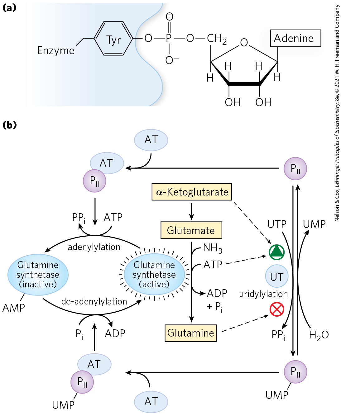
Superimposed on the allosteric regulation is inhibition by adenylylation of (addition of AMP to) , located near the enzyme’s active site (Fig. 22-9). This covalent modification increases sensitivity to the allosteric inhibitors, and activity decreases as more subunits are adenylylated. Both adenylylation and de-adenylylation are promoted by adenylyltransferase (AT in Fig. 22-9), part of a complex enzymatic cascade that responds to levels of glutamine, α-ketoglutarate, ATP, and . The activity of adenylyltransferase is modulated by binding to a regulatory protein called , and the activity of , in turn, is regulated by covalent modification (uridylylation), again at a Tyr residue. The adenylyltransferase complex with uridylylated (-UMP) stimulates de-adenylylation, whereas the same complex with deuridylylated stimulates adenylylation of glutamine synthetase. Both uridylylation and deuridylylation of are brought about by a single enzyme, uridylyltransferase. Uridylylation is inhibited by binding of glutamine and to uridylyltransferase and is stimulated by binding of α-ketoglutarate and ATP to .
FIGURE 22-9 Second level of regulation of glutamine synthetase: covalent modifications. (a) An adenylylated Tyr residue. (b) Cascade leading to adenylylation (inactivation) of glutamine synthetase. AT represents adenylyltransferase; UT, uridylyltransferase. is a regulatory protein, itself regulated by uridylylation.
The regulation does not stop there. The uridylylated also mediates the activation of transcription of the gene encoding glutamine synthetase, thus increasing the cellular concentration of the enzyme; the deuridylylated brings about a decrease in transcription of the same gene. This mechanism involves an interaction of with additional proteins involved in gene regulation, of a type described in Chapter 28. The net result of this elaborate system of controls is a decrease in glutamine synthetase activity when glutamine levels are high, and an increase in activity when glutamine levels are low and α-ketoglutarate and ATP (substrates for the synthetase reaction) are available. The multiple layers of regulation permit a sensitive response in which glutamine synthesis is tailored to cellular needs.
Several Classes of Reactions Play Special Roles in the Biosynthesis of Amino Acids and Nucleotides
The pathways described in this chapter include a variety of interesting chemical rearrangements. Several of these recur and deserve special note before we progress to the pathways themselves. These are (1) transamination reactions and other rearrangements promoted by enzymes containing pyridoxal phosphate; (2) transfer of one-carbon groups, with either tetrahydrofolate (usually at the and oxidation levels) or S-adenosylmethionine (at the oxidation level) as cofactor; and (3) transfer of amino groups derived from the amide nitrogen of glutamine. Pyridoxal phosphate (PLP), tetrahydrofolate ( folate), and S-adenosylmethionine (adoMet) are described in some detail in Chapter 18 (see Figs. 18-6, 18-17, and 18-18). Here we focus on amino group transfer involving the amide nitrogen of glutamine.
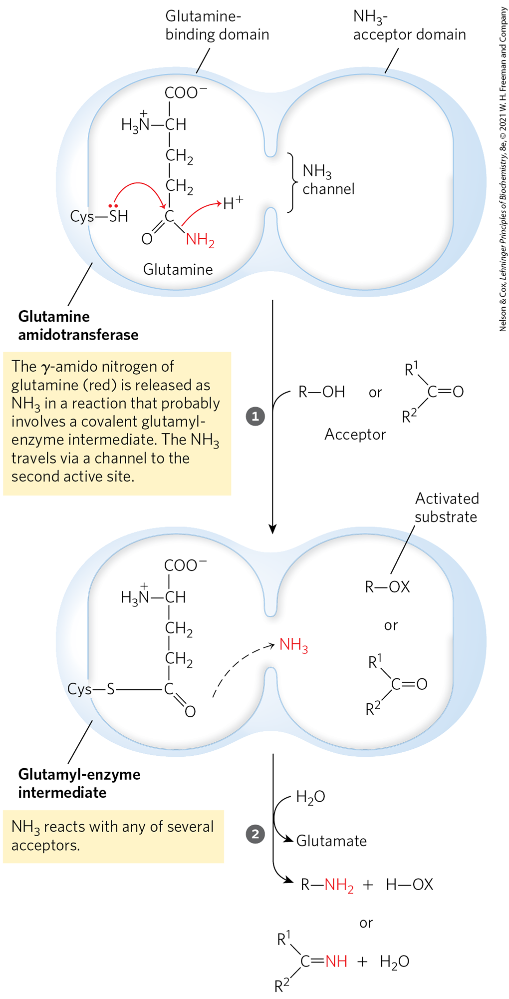
More than a dozen known biosynthetic reactions use glutamine as the major physiological source of amino groups, and most of these occur in the pathways outlined in this chapter. As a class, the enzymes catalyzing these reactions are called glutamine amidotransferases. All have two structural domains: one binding glutamine, the other binding the second substrate, which serves as amino group acceptor (Fig. 22-10). A conserved Cys residue in the glutamine-binding domain is believed to act as a nucleophile, cleaving the amide bond of glutamine and forming a covalent glutamyl-enzyme intermediate. The produced in this reaction is not released, but instead is transferred through an “ammonia channel” to a second active site, where it reacts with the second substrate to form the aminated product. The covalent intermediate is hydrolyzed to the free enzyme and glutamate. If the second substrate must be activated, the usual method is the use of ATP to generate an acyl phosphate intermediate ( in Fig. 22-10, where X is a phosphoryl group). The enzyme glutaminase acts similarly but uses as the second substrate, yielding and glutamate (see Fig. 18-8).
MECHANISM FIGURE 22-10 Proposed mechanism for glutamine amidotransferases. Each enzyme has two domains. The glutamine-binding domain contains structural elements conserved among many of these enzymes, including a Cys residue required for activity. The -acceptor (second-substrate) domain varies. Two types of amino acceptors are shown. X represents an activating group, typically a phosphoryl group derived from ATP, that facilitates displacement of a hydroxyl group from by .
SUMMARY 22.1 Overview of Nitrogen Metabolism
The molecular nitrogen that makes up 80% of Earth’s atmosphere is unavailable to most living organisms until it is reduced. A complex web of reactions converts atmospheric to biologically useful forms and maintains a global balance between them. Prominent species that are interconverted within this web include ammonia ( or ; most reduced), nitrite , and nitrate (; most oxidized). Conversion of to ammonia is fixation. Nitrification constitutes the steps converting ammonia to nitrate. Conversion of nitrate to constitutes denitrification. The alternative conversion of nitrate to ammonia is nitrate assimilation.
Fixation of as is carried out by the nitrogenase complex, in a reaction that requires large investments of ATP and of reducing power. The nitrogenase complex is highly labile in the presence of , and it is subject to regulation by the supply of .
In living systems, reduced nitrogen is incorporated first into amino acids and then into a variety of other biomolecules, including nucleotides. The key entry point is the amino acid glutamate. Glutamate and glutamine are the nitrogen donors in a wide range of biosynthetic reactions.
Glutamine synthetase, which catalyzes the formation of glutamine from glutamate, is a main regulatory enzyme of nitrogen metabolism.
The amino acid and nucleotide biosynthetic pathways make repeated use of the biological cofactors pyridoxal phosphate, tetrahydrofolate, and S-adenosylmethionine. Pyridoxal phosphate is required for transamination reactions involving glutamate and for other amino acid transformations. One-carbon transfers require S-adenosylmethionine and tetrahydrofolate. Glutamine amidotransferases catalyze reactions that incorporate nitrogen derived from the amide group of glutamine.
 Available amino acids, purines, and pyrimidines formed during metabolic turnover of proteins and nucleic acids are often salvaged and reused. We begin by examining the pathways by which nitrogen from the environment is introduced into biological systems.
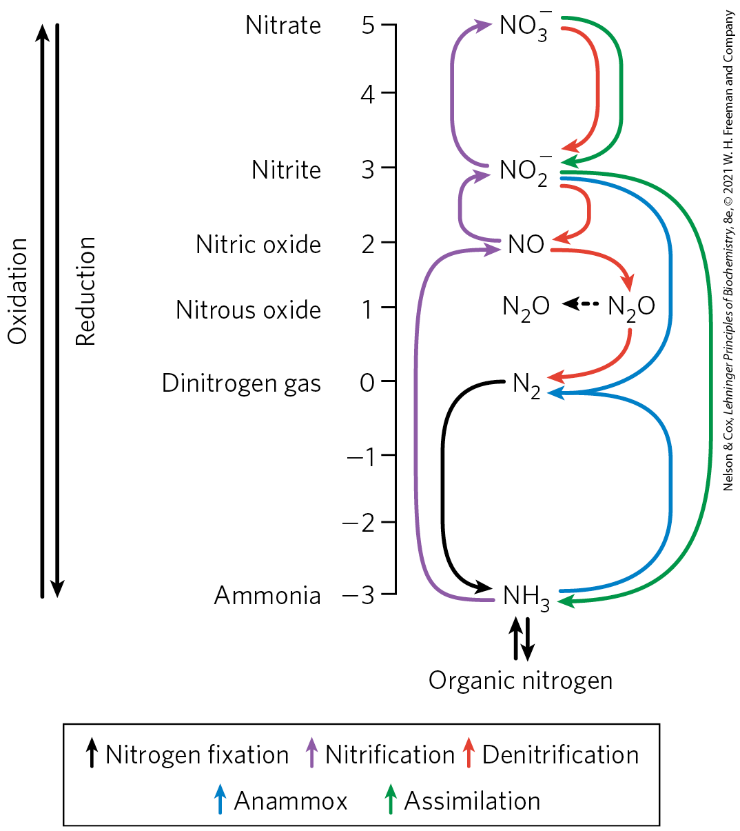
 Bacteria
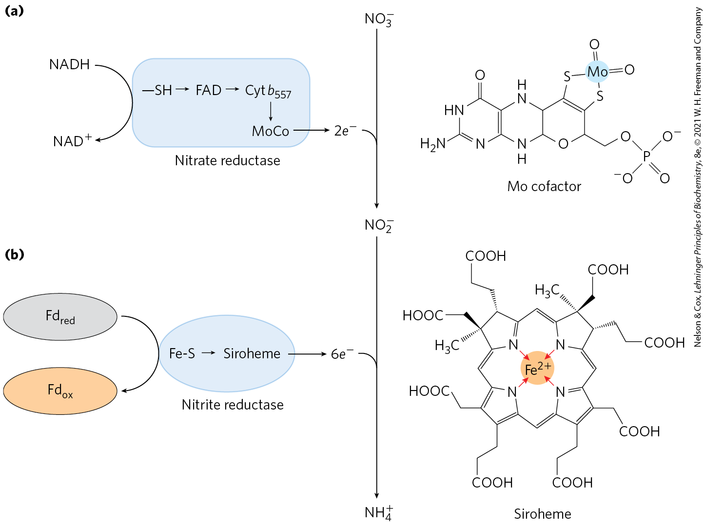
 Nonphotosynthetic
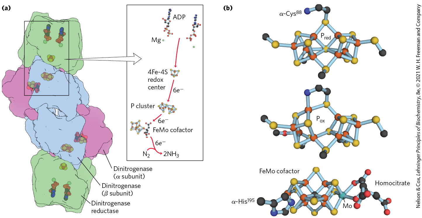
 Two amino acids, glutamate and glutamine, provide the critical entry point. Recall that these same two amino acids play central roles in the catabolism of ammonia and amino groups in amino acid oxidation (
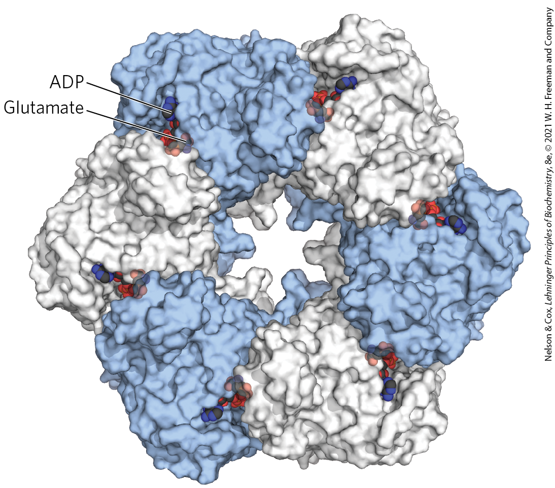
 Befitting their central metabolic role as an entry point for reduced nitrogen, GSI glutamine synthetases are highly regulated. In enteric bacteria such as E. coli, the regulation is unusually complex. Alanine, glycine, and at least six end products of glutamine metabolism are allosteric inhibitors (
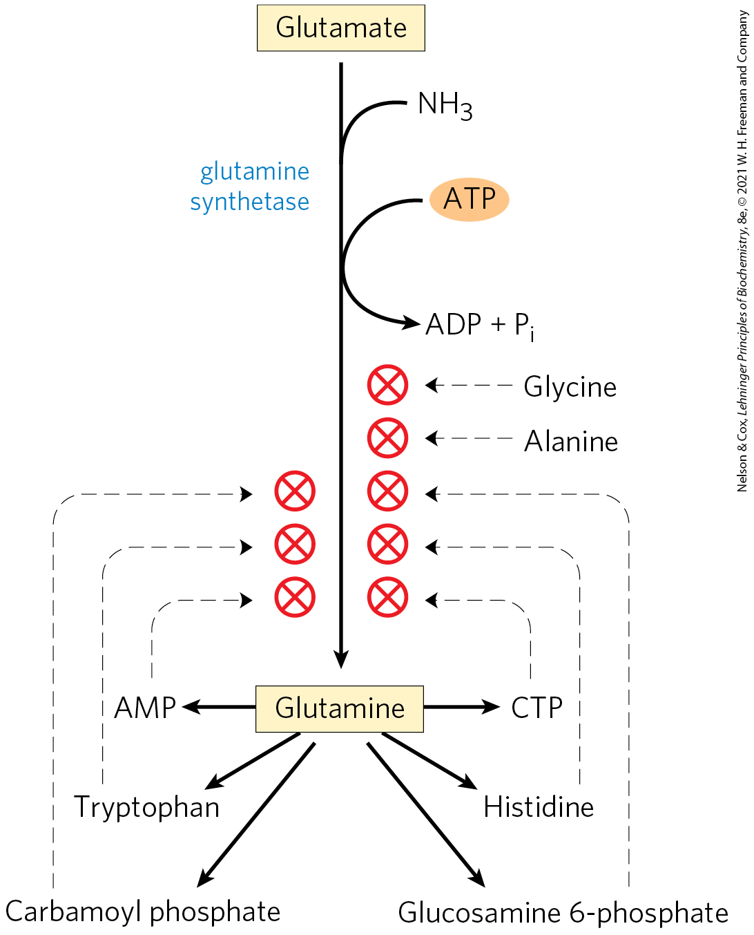
 The molecular nitrogen that makes up 80% of Earth’s atmosphere is unavailable to most living organisms until it is reduced. A complex web of reactions converts atmospheric to biologically useful forms and maintains a global balance between them. Prominent species that are interconverted within this web include ammonia ( or ; most reduced), nitrite , and nitrate (; most oxidized). Conversion of to ammonia is fixation. Nitrification constitutes the steps converting ammonia to nitrate. Conversion of nitrate to constitutes denitrification. The alternative conversion of nitrate to ammonia is nitrate assimilation.