Go to The Na+ Action Potential Tutorial
Click on start the simulation.
In the Panel & Graph Manager click on Patch Parameters.
Turn off Na+ and K+ voltage gated channels ( set density of both to 0.0 S/cm2 ).
Set time base to 100 ms (Run Control, Total # (ms) , 100 ms )
You now have a simplified situation with only one conductor in the membrane ( the so called leak conductance )
This leak conductance has a reversal potential of -54.3 mV.
Change Run Control, Reset ( mV ) to -54.3 mV.
1. First you will examine the influence of increasing current injection into the cell.
Make the current pulse duration 50 ms ( Stimulus Control , IClamp ).
Set delay to 10 ms.
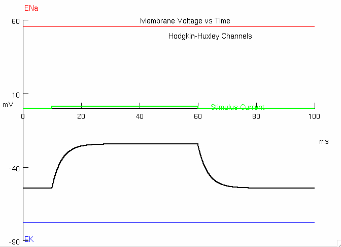
Set amplitude to 0.01414 n
This will cause a voltage change from -54 mV to -24 mV ( a 30 mV depolarization )
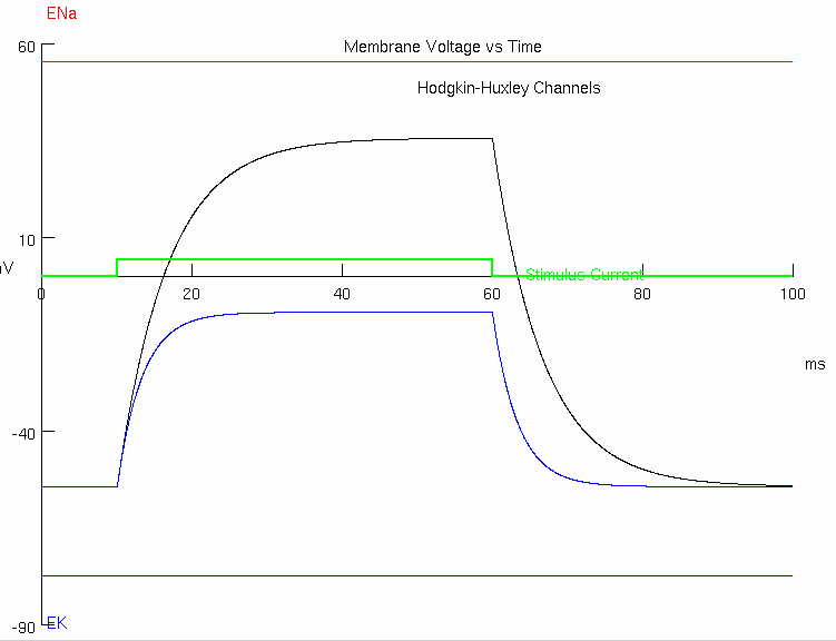
1A : Press "Reset and Run"
right click to "Keep Lines"
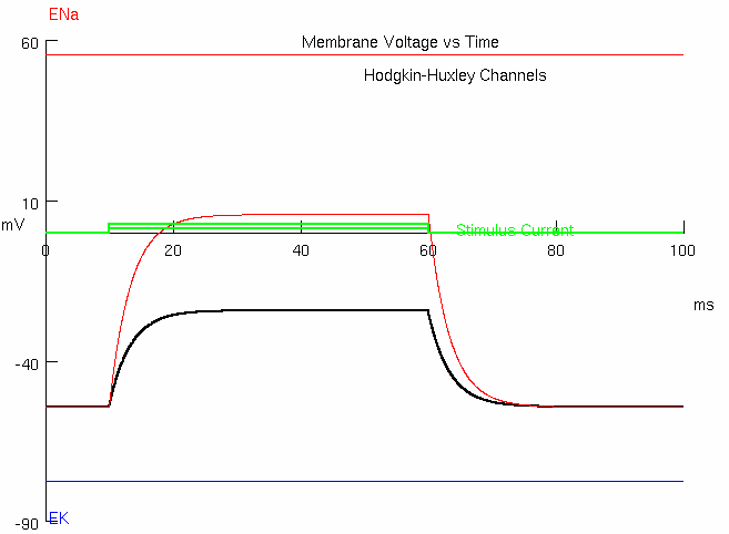
1B : Predict what will happen when you double the current amplitude to 0.02828 nA
Peak =
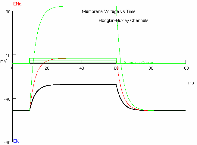
1C : Predict what happens when you quadruple the current to 0.05656 nA
Peak =
1D : Calculate the input resistance of this cell
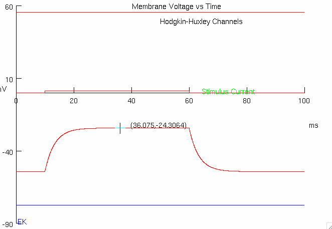
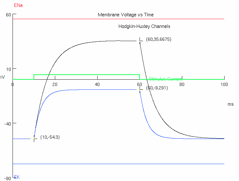
1E : Measure the time constant of this cell
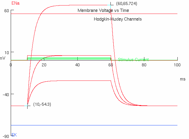
Measure initial , and peak y-values
initial = -54.3
final = +65.724
Calculate
find difference in y-values :
scale by approximately 63% of the value :
add this number to initial y-value :
find corresponding x-value to this calculated y-value :
subtract off any experiment stimulus delay to get final value :
( ( 65.724 ) - ( -54.3 ) ) * ( 1 - ( 1 / math.e ) ) + ( -54.3 )2. Now you will examine the influence of changing cell capacitance
set amplitude to 0.04242 nA
Press "Reset and Run"
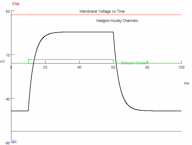
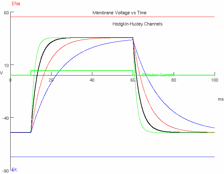
2A : Predict what happens as you change capacitance ( Patch Parameters )
try values of 0.5 , 1.0 , 2.0 , 4.0
green trace =
black trace =
red trace =
blue trace =
smaller capacitance = faster at charging and discharging
higher capacitance = slower at charging and discharging
2B : Discuss how changing capacitance alters input resistance
capacitance is not included in Ohm's law ,
or so it is not affected by input resistance
steady-state ( final ) voltage =
the total leak conductance input resistance is determined
2C : Discuss how changing capacitance alters the time constant
3. Now look at the responses of the cell to changing resistance ( 1 / conductance )
3A : Set the membrane capacitance at
press "Reset and Run"
3B : Double the leak conductance to
black trace =
blue trace =
Predict what happens to the steady state depolarization.
Discuss what happens to the time constant compared with the initial conductance level. ( This change may be hard to see easily )
time constant will decrease after increasing leak conductance
because time constant is directly proportional to resistance
but resistance is inverse of conductance , so
3C : Predict how much current you need to inject to make the depolarization the same , so you can directly compare time constants. ( Calculate what current you have to inject to get the same depolarization as when leak was only ½ as much ( original
Original Current =
Produced a
Original Leak Conductance =
therefore Original Leak Resistance :
for every
but now we want
replace
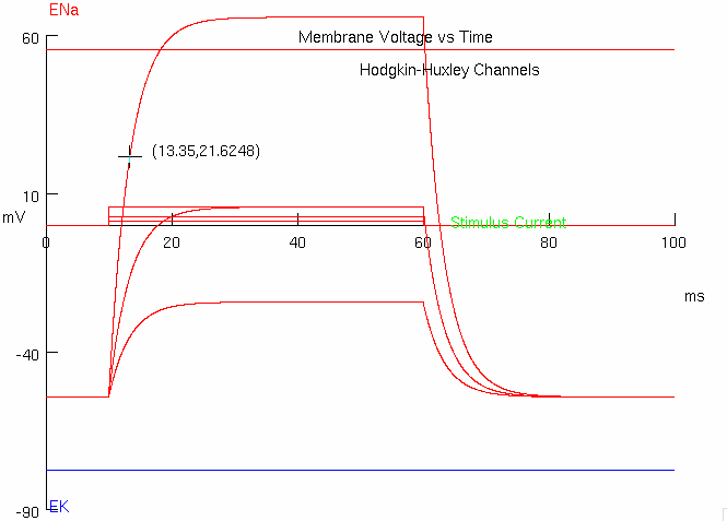
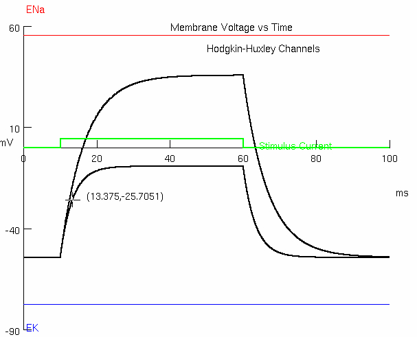
Measure the size of the time constant with the larger conductance.
initial = -54.3
final = -9.291
find difference in y-values :
take around 63% :
add to initial y-value :
find corresponding x-value :
13.375
3D : Predict what happens if you double leak again to 1.2 mS/cm2 ( 0.0012 S/cm2 )
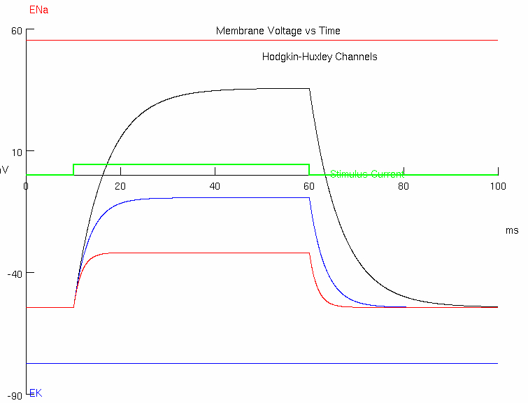
red trace =
Prediction = the resistance is lowered again by another factor of 2
Discuss what happens to the level of steady state depolarization.
the depolarization will be halved
3E : If you go back to your original leak conductance of 0.3 mS/cm2 ( 0.0003 S/cm2 ) , predict what the membrane would depolarize to
Calculate what current you have to inject to depolarize to +24 mV
Measure the time constant now and discuss
initial = -54.3
final = -31.7955
find difference in y-values :
take around 63% :
add to initial y-value :
find corresponding x-value :
11.675
the time constant is smaller with higher leak conductance
because higher leak conductance = lower resistance
lower resistance ➡️ faster charging and discharging