Chapter 16.1 - Figures
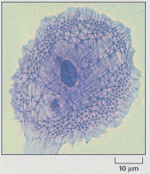
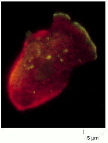
A cell in culture has been fixed and stained with Coomassie blue, a general stain for proteins. Note the variety of filamentous structures that extend throughout the cell. (Courtesy of Colin Smith.)
Chapter 16.2 - Figures
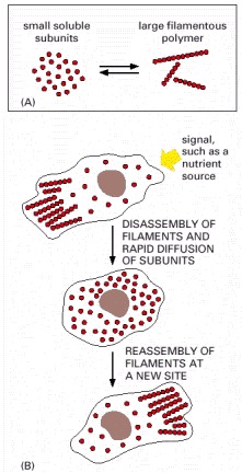
The formation of protein filaments from much smaller protein subunits allows regulated filament assembly and disassembly to reshape the cytoskeleton. (A) Filament formation from a small protein. (B) Rapid reorganization of the cytoskeleton in a cell in response to an external signal.
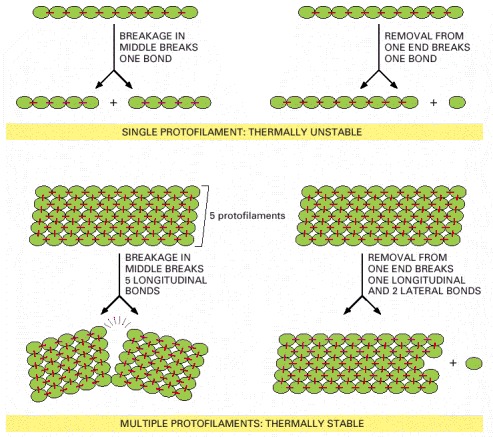
Formation of a cytoskeletal filament from more than one protofilament allows the ends to be dynamic, while the filaments themselves are resistant to thermal breakage. In this hypothetical example, the stable filament is formed from five protofilaments. The bonds holding the subunits together in the filaments are shown in red.
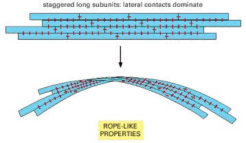
Intermediate filaments are formed in this way and are consequently especially resistant to bending or stretching forces.
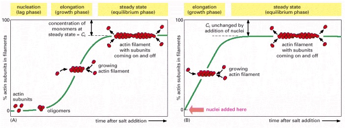
(A) Polymerization is begun by raising the salt concentration in a solution of pure actin subunits. (B) Polymerization is begun in the same way, but with preformed fragments of actin filaments present to act as nuclei for filament growth.
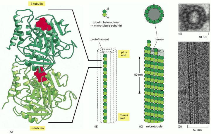
(A) The subunit of each protofilament is a tubulin heterodimer, formed from a very tightly linked pair of α- and β-tubulin monomers. The GTP molecule in the α-tubulin monomer is so tightly bound that it can be considered an integral part of the protein. The GTP molecule in the β-tubulin monomer, however, is less tightly bound and has an important role in filament dynamics. Both nucleotides are shown in red. (B) One tubulin subunit (α-β heterodimer) and one protofilament are shown schematically. Each protofilament consists of many adjacent subunits with the same orientation. (C) The microtubule is a stiff hollow tube formed from 13 protofilaments aligned in parallel. (D) A short segment of a microtubule viewed in an electron microscope. (E) Electron micrograph of a cross section of a microtubule showing a ring of 13 distinct protofilaments. (D, courtesy of Richard Wade; E, courtesy of Richard Linck.)
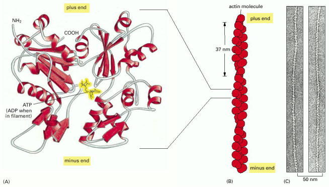
(A) The actin monomer has a nucleotide (either ATP or ADP) bound in a deep cleft in the center of the molecule. (B) Arrangement of monomers in a filament. Although the filament is often described as a single helix of monomers, it can also be thought of as consisting of two protofilaments, held together by lateral contacts, which wind around each other as two parallel strands of a helix, with a twist repeating every 37 nm. All the subunits within the filament have the same orientation. (C) Electron micrographs of negatively stained actin filaments. (C, courtesy of Roger Craig.)
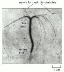
Both microtubules and actin filaments grow faster at one end than at the other. In this case, a stable bundle of microtubules obtained from the core of a cilium (discussed later) was incubated with tubulin subunits under polymerizing conditions. Microtubules grow fastest from the plus end of the microtubule bundle, the end at the top in this micrograph. (Courtesy of Gary Borisy.)
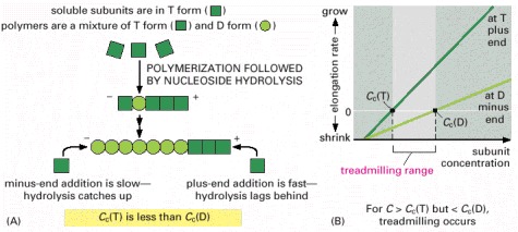
(A) Explanation for the different critical concentrations (Cc) at the plus and minus ends. Subunits with bound nucleoside triphosphate (T-form subunits) polymerize at both ends of a growing filament, and then undergo nucleotide hydrolysis in the filament lattice. As the filament grows, elongation is faster than hydrolysis at the plus end in this example, and the terminal subunits at this end are therefore always in the T form. However, hydrolysis is faster than elongation at the minus end, and so terminal subunits at this end are in the D form. (B) Treadmilling occurs at intermediate concentrations of free subunits. The critical concentration for polymerization on a filament end in the T form is lower than for a filament end in the D form. If the actual subunit concentration is somewhere between these two values, the plus end grows while the minus end shrinks, resulting in treadmilling.
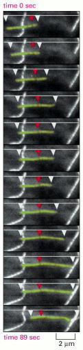
A cell was injected with tubulin that had been covalently linked to the fluorescent dye rhodamine, so that approximately 1 tubulin subunit in 20 was fluorescent. The fluorescence of individual microtubules was then observed with a sensitive electronic camera. The microtubule shown appears to be sliding from left to right, but, in fact, the microtubule lattice remains stationary (as shown by the dark mark indicated by the red arrowhead), while the plus end (on the right) grows and the minus end (on the left) shrinks. At the same time, the plus end is displaying dynamic instability. (From C.M. Waterman-Storer and E.D. Salmon, J. Cell Biol. 139:417–434, 1997. © The Rockefeller University Press.)
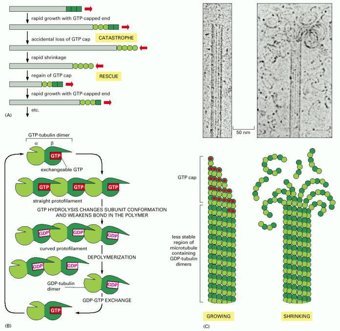
(A) If the free tubulin concentration in solution is between the critical values indicated in Figure 16-9, a single microtubule end may undergo transitions between a growing state and a shrinking state. A growing microtubule has GTP-containing subunits at its end, forming a GTP cap. If nucleotide hydrolysis proceeds more rapidly than subunit addition, the cap is lost and the microtubule begins to shrink, an event called a “catastrophe.” But GTP-containing subunits may still add to the shrinking end, and if enough add to form a new cap, then microtubule growth resumes, an event called “rescue.” (B) Model for the structural consequences of GTP hydrolysis in the microtubule lattice. The addition of GTP-containing tubulin subunits to the end of a protofilament causes the end to grow in a linear conformation that can readily pack into the cylindrical wall of the microtubule. Hydrolysis of GTP after assembly changes the conformation of the subunits and tends to force the protofilament into a curved shape that is less able to pack into the microtubule wall. (C) In an intact microtubule, protofilaments made from GDP-containing subunits are forced into a linear conformation by the many lateral bonds within the microtubule wall, given a stable cap of GTP-containing subunits. Loss of the GTP cap, however, allows the GDP-containing protofilaments to relax into their more curved conformation. This leads to a progressive disruption of the microtubule. Above the drawings of a growing and a shrinking microtubule, electron micrographs show actual microtubules in each of these two states, as observed in preparations in vitreous ice. Note particularly the curling, disintegrating GDP-containing protofilaments at the end of the shrinking microtubule. (C, courtesy of E.M. Mandelkow, E. Mandelkow and R.A. Milligan, J. Cell Biol. 114:977–991, 1991. © The Rockefeller University Press.)
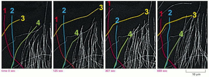
Microtubules in a newt lung epithelial cell were observed after the cell was injected with a small amount of rhodamine labeled tubulin, as in Figure 16-10. The dynamic instability of microtubules at the edge of the cell can be readily observed. Four individual microtubules are highlighted for clarity; each of these shows alternating shrinkage and growth. (Courtesy of Wendy C. Salmon and Clare Waterman-Storer.)
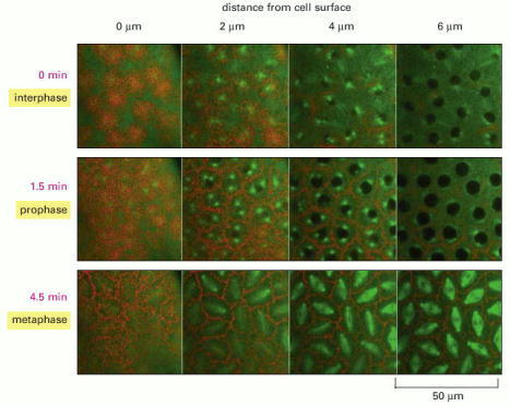
In this giant multinuclear cell, the early nuclear divisions occur every 10 minutes or so in a common cytoplasm. The rapid rearrangements of the actin filaments (red) and microtubules (green) seen here in a living embryo, are required to separate the chromosomes at mitosis, while keeping each nucleus from colliding with its neighbors. (Courtesy of William Sullivan.)
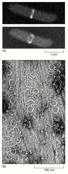
(A) A band of FtsZ protein forms a ring in a dividing bacterial cell. This ring has been labeled by fusing the FtsZ protein to the green fluorescent protein (GFP) and observing the living E. coli cells with a fluorescence microscope. Top, side view shows the ring as a bar in the middle of the dividing cell. Bottom, rotated view showing the ring structure. (B) FtsZ filaments and rings, formed in vitro, as visualized using electron microscopy. Compare this image with that of the microtubule shown on the right in Figure 16-11. (A, from X. Ma, D.W. Ehrhardt and W. Margolin, Proc. Natl. Acad. Sci. USA 93:12999–13003, 1996. © National Academy of Sciences; B, from H.A. Erickson et al., Proc. Natl. Acad. Sci. USA 93:519–523, 1996. © National Academy of Sciences.)
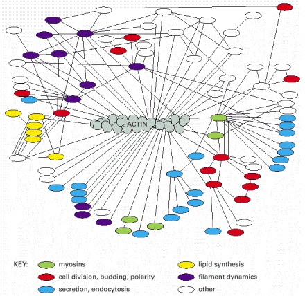
Actin binds to a very large variety of accessory proteins in all eucaryotic cells. This diagram shows most of the interactions that have been demonstrated, using either genetic or biochemical techniques, in the yeast Saccharomyces cerevisiae. Accessory proteins that operate in the same intracellular process are shown in the same color, as indicated in the key. (Adapted from D. Botstein et al., in The Molecular and Cellular Biology of the Yeast Saccharomyces [J.R. Broach, J.R. Pringle, E.W. Jones, eds.], Cold Spring Harbor, NY: Cold Spring Harbor Laboratory Press, 1991.)
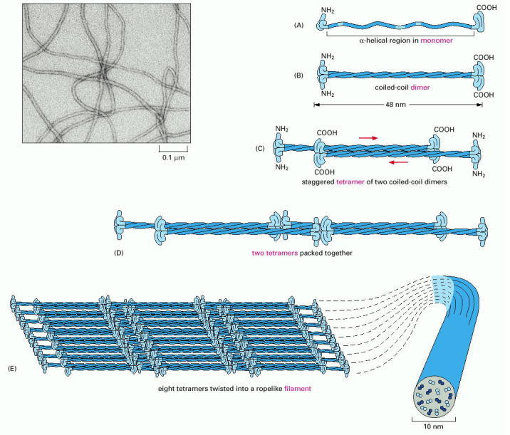
The monomer shown in (A) pairs with an identical monomer to form a dimer (B), in which the conserved central rod domains are aligned in parallel and wound together into a coiled coil. (C) Two dimers then line up side by side to form an antiparallel tetramer of four polypeptide chains. The tetramer is the soluble subunit of intermediate filaments. (D) Within each tetramer, the two dimers are offset with respect to one another, thereby allowing it to associate with another tetramer. (E) In the final 10-nm rope-like filament, tetramers are packed together in a helical array, which has 16 dimers in cross-section. Half of these dimers are pointing in each direction. An electron micrograph of intermediate filaments are shown on the upper left. (Electron micrograph courtesy of Roy Quinlan.)
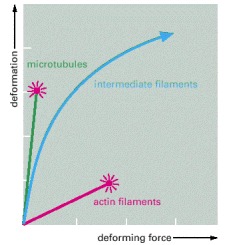
Networks composed of microtubules, actin filaments, or a type of intermediate filament called vimentin, all at equal concentration, were exposed to a shear force in a viscometer, and the resulting degree of stretch was measured. The results show that microtubule networks are easily deformed but that they rupture (indicated by red starburst) and begin to flow without limit when stretched beyond 150% of their original length. Actin filament networks are much more rigid, but they also rupture easily. Intermediate filament networks, by contrast, are not only easily deformed, but they withstand large stresses and strains without rupture; they are thereby well suited to maintain cell integrity. (Adapted from P. Janmey et al., J. Cell Biol. 113:155–160, 1991.)
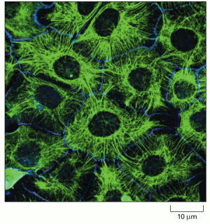
Immunofluorescence micrograph of the network of keratin filaments (green) in a sheet of epithelial cells in culture. The filaments in each cell are indirectly connected to those of its neighbors by desmosomes (discussed in Chapter 19). A second protein (blue) has been stained to reveal the location of the cell boundaries. (Courtesy of Kathleen Green and Evangeline Amargo.)
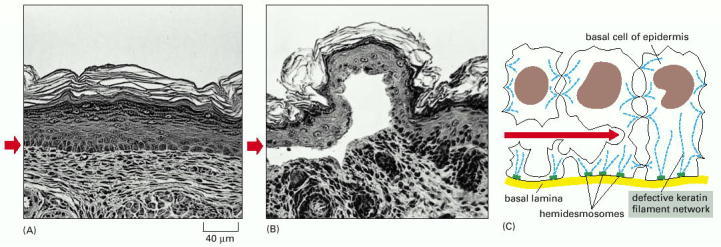
A mutant gene encoding a truncated keratin protein (lacking both the N- and C-terminal domains) was expressed in a transgenic mouse. The defective protein assembles with the normal keratins and thereby disrupts the keratin filament network in the basal cells of the skin. Light micrographs of cross sections of normal (A) and mutant (B) skin show that the blistering results from the rupturing of cells in the basal layer of the mutant epidermis (small red arrows). (C) A sketch of three cells in the basal layer of the mutant epidermis, as observed by electron microscopy. As indicated by the red arrow, the cells rupture between the nucleus and the hemidesmosomes (discussed in Chapter 19), which connect the keratin filaments to the underlying basal lamina. (From P.A. Coulombe et al., J. Cell Biol. 115:1661–1674, 1991. © The Rockefeller University Press.)
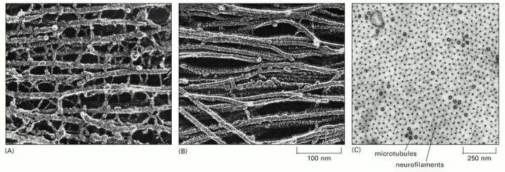
(A) Freeze-etch electron microscopic image of neurofilaments in a nerve cell axon, showing the extensive cross-linking through protein cross-bridges—an arrangement believed to give this long cell process great tensile strength. The cross-bridges are formed by the long, nonhelical extensions at the C-terminus of the largest neurofilament protein (NF-H). (B) Freeze-etch image of glial filaments in glial cells, showing that these intermediate filaments are smooth and have few cross-bridges. (C) Conventional electron micrograph of a cross section of an axon showing the regular side-to-side spacing of the neurofilaments, which greatly outnumber the microtubules. (A and B, courtesy of Nobutaka Hirokawa; C, courtesy of John Hopkins.)
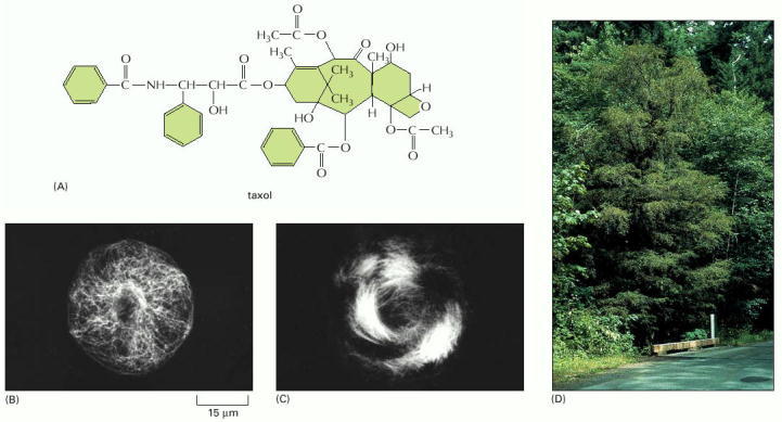
(A) Molecular structure of taxol. Recently, organic chemists have succeeded in synthesizing this complex molecule, which is widely used for cancer treatment. (B) Immunofluorescence micrograph showing the microtubule organization in a liver epithelial cell before the addition of taxol. (C) Microtubule organization in the same type of cell after taxol treatment. Note the thick circumferential bundles of microtubules around the periphery of the cell. (D) A Pacific yew tree, the natural source of taxol. (B, C from N.A. Gloushankova et al., Proc. Natl. Acad. Sci. USA 91:8597–8601, 1994. © National Academy of Sciences; D, courtesy of A.K. Mitchell 2001. © Her Majesty the Queen in Right of Canada, Canadian Forest Service.)
Chapter 16.3 - Figures
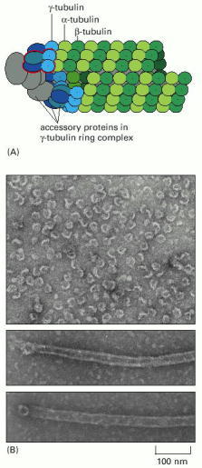
(A) Model for the nucleation of microtubule growth by the γ-TuRC. The red outline indicates a pair of proteins bound to two molecules of γ-tubulin; this group can be isolated as a separate subcomplex of the larger ring. (B) Electron micrographs of purified γ-tubulin ring complexes (top) and single microtubules nucleated from the purified γ-tubulin ring complexes (middle and bottom). (A, modified from M. Moritz et al., Nature Cell Biol. 2:365–370, 2000; B, courtesy of Y. Zheng et al., Nature 378:578–583, 1994. © Macmillan Magazines Ltd.)
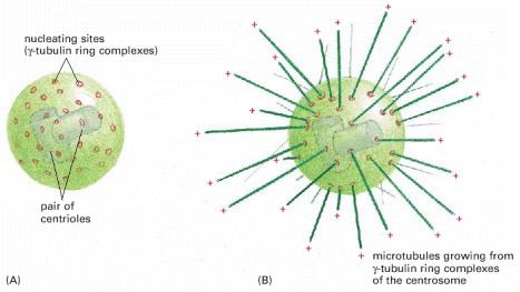
(A) The centrosome is the major MTOC of animal cells. Located in the cytoplasm next to the nucleus, it consists of an amorphous matrix of protein containing the γ-tubulin ring complexes that nucleate microtubule growth. This matrix is organized by a pair of centrioles, as described in the text. (B) A centrosome with attached microtubules. The minus end of each microtubule is embedded in the centrosome, having grown from a γ-tubulin ring complex, whereas the plus end of each microtubule is free in the cytoplasm.
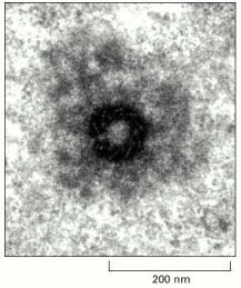
An electron micrograph of a thick section of a centrosome showing an end-on view of a centriole. The ring of modified microtubules of the centriole is visible, surrounded by the fibrous centrosome matrix. (Courtesy of P. Witt and G.G. Borisy.)
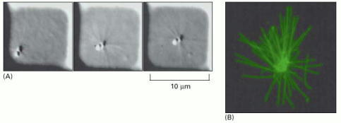
(A) Small square wells were micromachined into a plastic substrate. A single centrosome was placed into one of these wells, along with tubulin subunits in solution. As the microtubules polymerize, nucleated by the centrosome, they push against the walls of the well. The requirement for equal pushing in all directions if the position is to be stabilized forces the centrosome to the center of the well. The three pictures were taken at three-minute intervals. (B) A similar self-centered centrosome, fixed and stained to show the distribution of the microtubules pushing on all four walls of the enclosure. (From T.E. Holy et al., Proc. Natl. Acad. Sci. USA 94:6228–6231, 1997. © National Academy of Sciences.)
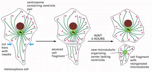
After the arm of a fish pigment cell is cut off with a needle, the microtubules in the detached cell fragment reorganize so that their minus ends end up near the center of the fragment, buried in a new microtubule-organizing center.
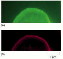
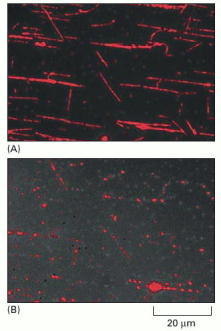
Fibroblasts in culture were gently permeabilized using a nonionic detergent and were then incubated with rhodamine-labeled actin molecules to visualize newly formed actin filaments (red). After 5 minutes, the cells were fixed and stained with fluorescein-labeled phalloidin to stain all actin filaments (green). (A) All of the actin filaments, most of which were formed before the cells were permeabilized, are shown in green. (B) The location of the newly formed actin filaments (red) show that the leading edge is the predominant site of actin filament assembly in the cell. Further studies show that this is because new actin filaments are constantly being nucleated here. (From M.H. Symons and T.J. Mitchison, J. Cell Biol. 114:503–513, 1991. © The Rockefeller University Press.)
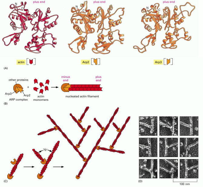
(A)The structures of Arp2 and Arp3, compared to the structure of actin. Although the face of the molecule equivalent to the plus end (top) in both Arp2 and Arp3 is very similar to the plus end of actin itself, differences on the sides and minus end (bottom) prevent these actin-related proteins from forming filaments on their own or coassembling into filaments with actin. (B) A model for actin filament nucleation by the ARP complex. Arp2 and Arp3 may be held by their accessory proteins in an orientation that resembles the plus end of an actin filament. Actin subunits can then assemble onto this structure, bypassing the rate-limiting step of filament nucleation (see Figure 16-5). (C) The ARP complex nucleates filaments more efficiently when it is bound to the side of a preexisting actin filament. The result is a filament branch that grows at a 70° angle relative to the original filament. Repeated rounds of branching nucleation result in a treelike web of actin filaments. (D) Electron micrographs of branched actin filaments formed by mixing purified actin subunits with purified ARP complexes. (D, courtesy of R.D. Mullins et al., Proc. Natl. Acad. Sci. USA 95:6181–6186, 1998. © National Academy of Sciences.)
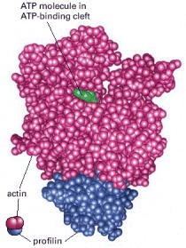
The profilin protein molecule is shown in blue, and the actin in red. ATP is shown in green. Profilin binds to the face of actin opposite the ATP-binding cleft. This profilin-actin heterodimer can therefore bind to and elongate the plus end of an actin filament, but it is sterically prevented from binding to the minus end. (Courtesy of Michael Rozycki and Clarence E. Schutt.)
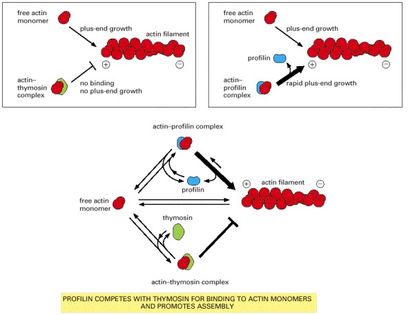
An actin monomer bound to thymosin is sterically prevented from binding to and elongating the plus end of an actin filament. An actin monomer bound to profilin, on the other hand, is capable of elongating a filament. Thymosin and profilin cannot both bind to a single actin monomer at the same time. In a cell in which most of the actin monomer is bound to thymosin, the activation of a small amount of profilin can produce rapid filament assembly. As indicated, profilin binds to actin monomers that are transiently released from the thymosin-bound monomer pool, shuttles them onto the plus ends of actin filaments, and is then released and recycled for further rounds of filament elongation.
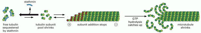
Polymerization of free tubulin subunits to form microtubules is an energetically favorable reaction. As long as abundant free tubulin subunits are available, microtubule elongation continues. Stathmin sequesters free tubulin subunits, binding two tubulin αβ-heterodimers per stathmin molecule. As the pool of free tubulin subunits shrinks, microtubule elongation slows. This makes it more likely that the rate of GTP hydrolysis will catch up with the rate of subunit addition, and the GTP cap will be lost, resulting in a transition of the microtubule from the growing state to the shrinking state. Stathmin has a second activity that promotes this transition, which involves a direct interaction with a microtubule plus end (not shown). Stathmin is also called “oncoprotein 18,” since its expression level is frequently increased in tumor cells, resulting in increased turnover of microtubules.
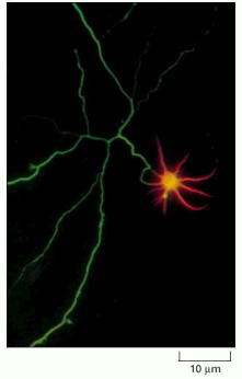
This immunofluorescence micrograph shows the distribution of tau staining (green) and MAP2 staining (orange) in a hippocampal neuron in culture. Whereas tau staining is confined to the axon (long and branched in this neuron), MAP2 staining is confined to the cell body and its dendrites. The antibody used here to detect tau binds only to unphosphorylated tau; phosphorylated tau is also present in dendrites. (Courtesy of James W. Mandell and Gary A. Banker.)
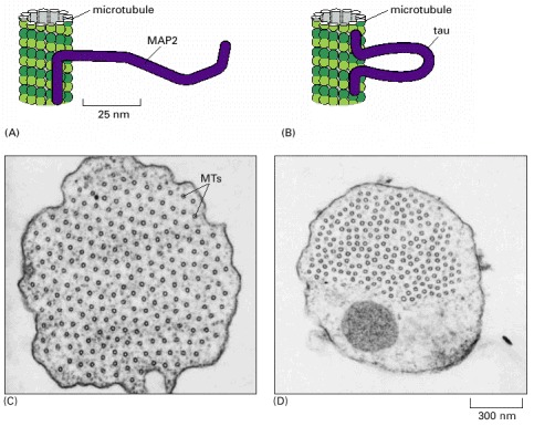
(A) MAP2 binds along the microtubule lattice at one end and extends a long projecting arm with a second microtubule-binding domain at the other end. (B) Tau binds to the microtubule lattice at both its N- and C-termini, with a short projecting loop. (C) Electron micrograph showing a cross section through a microtubule bundle in a cell overexpressing MAP2. The regular spacing of the microtubules (MTs) in this bundle result from the constant length of the projecting arms of the MAP2. (D) Similar cross section through a microtubule bundle in a cell overexpressing tau. Here the microtubules are spaced more closely together than they are in (C) because of tau's relatively short projecting arm. (C and D, courtesy of V. Chen et al., Nature 360:674–647, 1992. © Macmillan Magazines Ltd.)
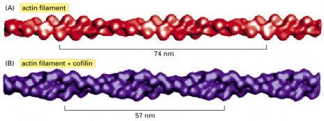
(A) Three-dimensional reconstruction from cryo-electron micrographs of filaments made of pure actin. The bracket shows the span of two turns of the actin helix. (B) Reconstruction of an actin filament coated with cofilin, which binds in a 1:1 stoichiometry to actin subunits all along the filament. Cofilin is a small protein (14 kilodaltons) compared to actin (43 kilodaltons), and so the filament appears only slightly thicker. The energy of cofilin binding serves to deform the actin filament lattice, twisting it more tightly so that the distance spanned by two turns of the helix is reduced. (From A. McGough et al., J. Cell Biol. 138:771–781, 1997. © The Rockefeller University Press.)
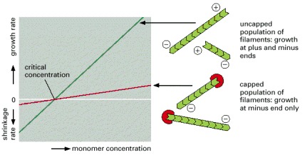
A population of uncapped filaments adds and loses subunits at both the plus and minus ends, resulting in rapid growth or shrinkage, depending on the concentration of available free monomers (green line). In the presence of a protein that caps the plus end (red line), only the minus end is able to add or lose subunits; consequently, filament growth will be slower at all monomer concentrations above the critical concentration, and filament shrinkage will be slower at all monomer concentrations below the critical concentration. Plus-end capping of this type is widely used for actin filaments but not for microtubules.
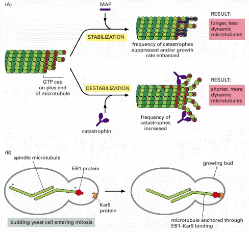
(A) The transition between microtubule growth and microtubule shrinking is controlled in cells by special proteins. A MAP such as XMAP215 stabilizes the end of a growing microtubule by its preferential binding there. Opposing its action are members of the kinesin superfamily (discussed later) designated here as catastrophins, but called by a variety of other names (such as, the Kin1 family that includes KIF2 in Figure 16-55). (B) Capping proteins help to localize microtubules. Here, the EBI microtubule capping protein interacts with localized Kar9 proteins in the budding yeast Saccharomyces cerevisiae. This interaction directs spindle microtubules into the growing bud during mitosis. A mutation in either protein causes the indicated spindle microtubules to lose their way. The EB1 protein is also found on the plus ends of microtubules in human cells.
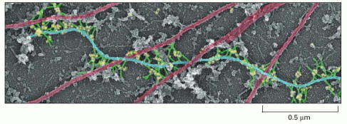
Plectin (green) makes cross-links from intermediate filaments (blue) to other intermediate filaments, to microtubules (red), and to myosin thick filaments. In this electron micrograph, the dots (yellow) are gold particles linked to anti-plectin antibodies. The entire actin filament network was removed to reveal these proteins. (From T.M. Svitkina and G.G.Borisy, J. Cell Biol. 135:991–1007, 1996. © The Rockefeller University Press.)
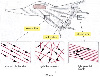
A crawling cell, drawn to scale, is shown with three areas enlarged to show the arrangement of actin filaments. The actin filaments are shown in red, with arrowheads pointing toward the plus end. Stress fibers are contractile and exert tension. Filopodia are spike-like projections of the plasma membrane that allow a cell to explore its environments. The cortex underlies the plasma membrane.
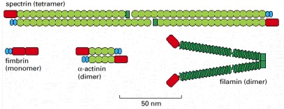
Each of the proteins shown has two actin-binding sites (red) that are related in sequence. Fimbrin has two directly adjacent actin-binding sites, so that it holds its two actin filaments very close together (14 nm apart), aligned with the same polarity (see Figure 16-40A). The two actin-binding sites in α-actinin are separated by a spacer around 30 nm long, so that it forms more loosely packed actin bundles (see Figure 16-40). Filamin has two actin-binding sites with a V-shaped linkage between them, so that it cross-links actin filaments into a network with the filaments oriented almost at right angles to one another (see Figure 16-42). Spectrin is a tetramer of two α and two β subunits, and the tetramer has two actin-binding sites spaced about 200 nm apart (see Figure 10-31).
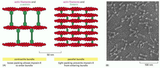
(A) α-actinin, which is a homodimer, cross-links actin filaments into loose bundles, which allow the motor protein myosin II (not shown) to participate in the assembly. Fimbrin cross-links actin filaments into tight bundles, which exclude myosin. Fimbrin and α-actinin tend to exclude one another because of the very different spacing of the actin filament bundles that they form. (B) Electron micrograph of purified α-actinin molecules. (B, courtesy of John Heuser.)
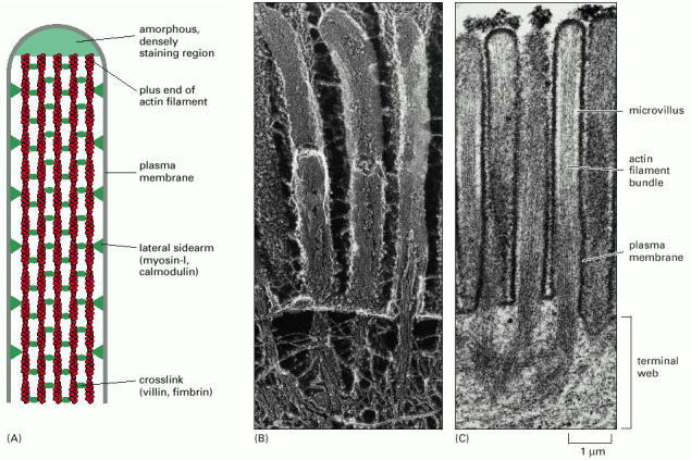
(A) A bundle of parallel actin filaments cross-linked by the actin-bundling proteins villin and fimbrin forms the core of a microvillus. Lateral sidearms (composed of myosin I and the Ca2+-binding protein calmodulin) connect the sides of the actin filament bundle to the overlying plasma membrane. All the plus ends of the actin filaments are at the tip of the microvillus, where they are embedded in an amorphous, densely staining substance of unknown composition. (B) Freeze-fracture electron micrograph of the apical surface of an intestinal epithelial cell, showing microvilli. Actin bundles from the microvilli extend down into the cell and are rooted in the terminal web, where they are linked together by a complex set of proteins that includes spectrin and myosin II. Below the terminal web is a layer of intermediate filaments. (C) Thin section electron micrograph of microvilli. (B, courtesy of John Heuser; C, from P.T. Matsudaira and D.R. Burgess, Cold Spring Harbor Symp. Quant. Biol. 46:845–854, 1985.)
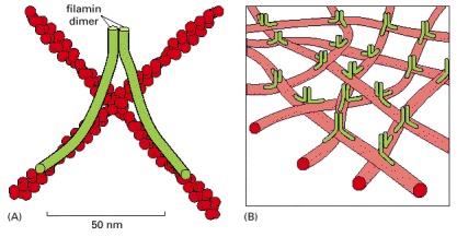
(A) Each filamin homodimer is about 160 nm long when fully extended and forms a flexible, high-angle link between two adjacent actin filaments. (B) A set of actin filaments cross-linked by filamin forms a mechanically strong web or gel.
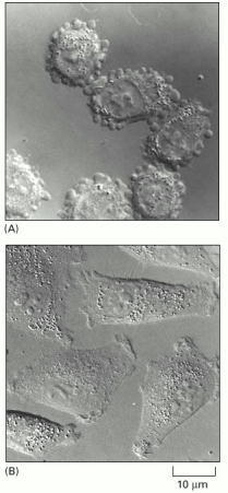
(A) A group of melanoma cells that have an abnormally low level of filamin. These cells are not able to make normal lamellipodia and instead are covered with membrane “blebs.” As a result, they crawl poorly and tend not to metastasize. (B) The same melanoma cells in which filamin expression has been artificially restored. The cells now make normal lamellipodia and are highly metastatic. This example is one of many demonstrating the profound effect that the presence or absence of a single structural protein can have on cell morphology and motility. (From C. Cunningham et al., J. Cell Biol. 136:845–857, 1997. © The Rockefeller University Press.)
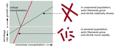
Normally, filaments are able to gain and lose subunits only at their ends, limiting the maximum rates of growth and shrinkage of the total amount of actin in filamentous form (green line). If the filaments are severed into smaller pieces, the number of ends increases, so the increase in filament mass in the population can be faster at all monomer concentrations above the critical concentration, and the decrease in filament mass in the population can also be faster at all monomer concentrations below the critical concentration (red line). Thus, severing enhances the rate of filament dynamics.
Taxol-stabilized, rhodamine-labeled microtubules were adsorbed on the surface of a glass slide, and purified katanin was added along with ATP. (A) There are a few breaks in the microtubules 30 seconds after the addition of katanin. (B) The same field 3 minutes after the addition of katanin. The filaments have been severed in many places, leaving a series of small fragments at the previous locations of the long microtubules. (From J.J. Hartman et al., Cell 93:277–287, 1998. © Elsevier.)
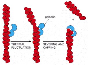
There are two actin-binding sites in the gelsolin protein. These sites allow gelsolin to bind both along the side and at the end of an actin filament. Filaments that have been severed by gelsolin remain capped at their plus ends. Villin, an actin-bundling protein (see Figure 16-41A), is a member of the same protein family as gelsolin, but it has gained another actin-binding site and lost its ability to sever filaments except at very high (nonphysiological) Ca2+ concentrations.
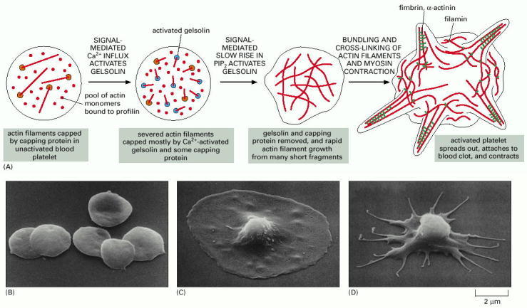
(A) Platelet activation is a controlled sequence of actin filament severing, uncapping, elongation, recapping, and cross-linking that creates a dramatic shape change in the platelet. (B) Scanning electron micrograph of platelets prior to activation. (C) An activated platelet with its large spread lamellipodium. (D) An activated platelet at a later stage than the one shown in C, after myosin II-mediated contraction. (Courtesy of James G. White.)
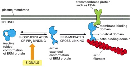
Regulated unfolding of an ERM-family protein, caused by phosphorylation or by binding to PIP2, exposes two binding sites, one for an actin filament and one for a transmembrane protein. Activation of ERM-family proteins can thereby generate and stabilize cell-surface protrusions that form in response to extracellular signals.
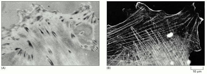
(A) Focal contacts are best seen in living cells by reflection-interference microscopy. In this technique, light is reflected from the lower surface of a cell attached to a glass slide, and the focal contacts appear as dark patches. (B) Immunofluorescence staining of the same cell (after fixation) with antibodies to actin shows that most of the cell's actin filament bundles (or stress fibers) terminate at or close to a focal contact. (Courtesy of Grenham Ireland.)
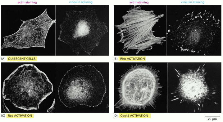
In each case, the actin filaments have been labeled with fluorescent phalloidin, and focal contacts have been located with an antibody against vinculin. (A) Serum-starved fibroblasts have actin filaments primarily in the cortex, and relatively few focal contacts. (B) Microinjection of a constitutively activated form of Rho causes the rapid assembly of many prominent stress fibers and focal contacts. (C) Microinjection of a constitutively activated form of Rac, a closely related monomeric GTPase, causes the formation of an enormous lamellipodium that extends from the entire circumference of the cell. (D) Microinjection of a constitutively activated form of Cdc42, another Rho family member, causes the protrusion of many long filopodia at the cell periphery that form adhesive contacts with the substratum. The distinct global effects of these three GTPases on the organization of the actin cytoskeleton are mediated by the actions of dozens of other protein molecules that are regulated by the GTPases. Many of these target proteins resemble the various actin-associated proteins that we have discussed in this chapter. (From A. Hall, Science 279:509–514, 1998. © AAAS.)
Chapter 16.4 - Figures
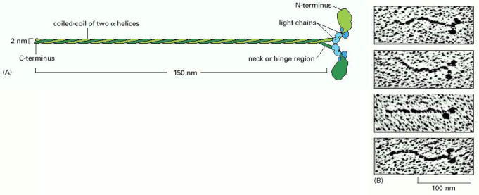
(A) A myosin II molecule is composed of two heavy chains (each about 2000 amino acids long (green) and four light chains (blue). The light chains are of two distinct types, and one copy of each type is present on each myosin head. Dimerization occurs when the two α helices of the heavy chains wrap around each other to form a coiled-coil, driven by the association of regularly spaced hydrophobic amino acids (see Figure 3-11). The coiled-coil arrangement makes an extended rod in solution, and this part of the molecule is called the tail. (B) The two globular heads and the tail can be clearly seen in electron micrographs of myosin molecules shadowed with platinum. (B, courtesy of David Shotton.)
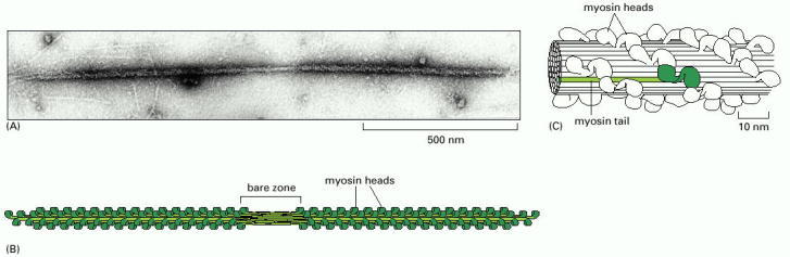
(A) Electron micrograph of a myosin II thick filament isolated from frog muscle. Note the central bare zone, which is free of head domains. (B) Schematic diagram, not drawn to scale. The myosin II molecules aggregate by means of their tail regions, with their heads projecting to the outside of the filament. The bare zone in the center of the filament consists entirely of myosin II tails. (C) A small section of a myosin II filament as reconstructed from electron micrographs. An individual myosin molecule is highlighted in green. (A, courtesy of Murray Stewart; C, based on R.A. Crowther, R. Padron and R. Craig, J. Mol. Biol. 184:429–439, 1985. © Academic Press.)
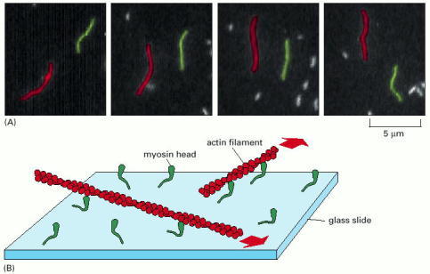
In this experiment, purified S1 myosin heads were attached to a glass slide, and then actin filaments labeled with fluorescent phalloidin were added and allowed to bind to the myosin heads. (A) When ATP was added, the actin filaments began to glide along the surface, owing to the many individual steps taken by each of the dozens of myosin heads bound to each filament. The video frames shown in this sequence were recorded about 0.6 second apart; the two actin filaments shown (one red and one green) were moving in opposite directions at a rate of about 4 μm/sec. (B) Diagram of the experiment. The large red arrows indicate the direction of actin filament movement. (A, courtesy of James Spudich.)
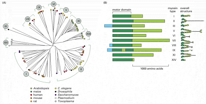
(A) A family tree for a few of the many known members of the myosin superfamily. The length of the lines separating individual family members indicates the amount of difference in the amino acid sequence of the motor domain. Groups of related myosins that share a similar structure are assigned a Roman numeral. The species of origin of some of the myosins shown are indicated with colored dots. Some myosin types (such as I and II) have members in many eucaryotic species, ranging from animals to plants to parasitic protozoa; others are found only in particular groups of eucaryotes (XIV, for example, has been found so far only in parasitic protozoa such as Toxoplasma and Plasmodium). (B) Comparison of the domain structure of the heavy chains of some myosin types. All myosins share similar motor domains (shown in dark green), but their C-terminal tails (light green) and N-terminal extensions (light blue) are very diverse. On the right are depictions of the molecular structure for these family members. Many myosins form dimers, with two motor domains per molecule, but a few (such as I, IX, and XIV) seem to function as monomers, with just one motor domain. Myosin VI, despite its overall structural similarity to other family members, is unique in moving toward the minus end (instead of the plus end) of an actin filament. The small insertion within its motor head domain, not found in other myosins, is probably responsible for this change in direction.
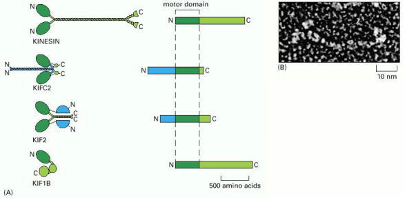
(A) Structures of four kinesin superfamily members. As in the myosin superfamily, only the motor domains are conserved. Conventional kinesin has the motor domain at the N-terminus of the heavy chain. The middle domain forms a long coiled-coil, mediating dimerization. The C-terminal domain forms a tail that attaches to cargo, such as a membrane-enclosed organelle. KIFC2 is a member of a family of C-terminal kinesins that includes the Drosophila protein Ncd and the yeast protein KAR3. These kinesins generally travel in the opposite direction from the majority of kinesins, toward the minus end instead of the plus end of a microtubule. KIF2 has its motor domain located in the middle of the heavy chain. It is a member of a family of kinesins that have lost typical motor activity and instead bind to microtubule ends to increase dynamic instability of microtubules; they are therefore called catastrophins. KIF1B is a member of the unusual class of kinesins that seem to function as monomers and move membrane-enclosed organelles along microtubules. Not shown is the BimC family of kinesins, which form tetramers. (B) Freeze-etch electron micrograph of a kinesin molecule with the head domains on the left. (B, courtesy of John Heuser.)
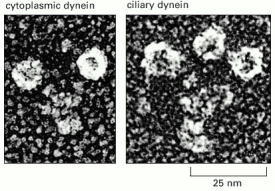
Freeze-etch electron micrographs of a molecule of cytoplasmic dynein and a molecule of ciliary (axonemal) dynein. Like myosin II and kinesin, cytoplasmic dynein is a two-headed molecule. The ciliary dynein shown has three heads. Note that the dynein head is very large compared with the head of either myosin or kinesin. (Courtesy of John Heuser.)
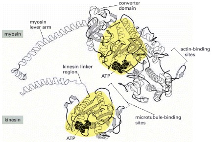
The central nucleotide-binding domains of myosin and kinesin (shaded in yellow) are structurally very similar. The very different sizes and functions of the two motors are due to major differences in the polymer-binding and force-transduction portions of the motor domain. (Adapted from L.A. Amos and R.A. Cross, Curr. Opin. Struct. Biol. 7:239–246, 1997.)
(Based on I. Rayment et al., Science 261:50–58, 1993. © AAAS.)
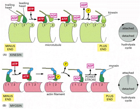
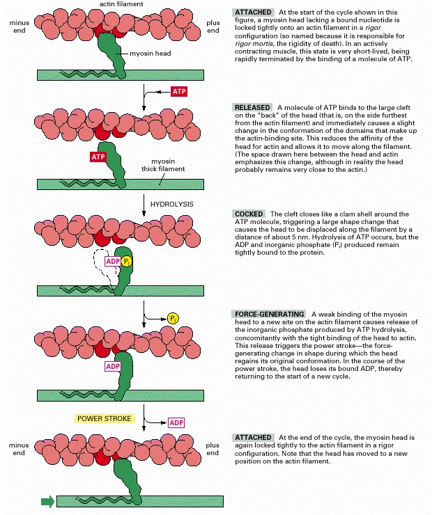
The shading in the two circles representing the hydrolysis cycle indicates the proportion of the cycle spent in attached and detached states for each motor protein. (A) Summary of the coupling between ATP hydrolysis and conformational changes for kinesin. At the start of the cycle, one of the two kinesin heads, the front or leading head (dark green) is bound to the microtubule, with the rear or trailing head (light green) detached. Binding of ATP to the front head causes the rear head to be thrown forward, past the binding site of the attached head, to another binding site further toward the plus end of the microtubule. Release of ADP from the second head (now in the front) and hydrolysis of ATP on the first head (now in the rear) brings the dimer back to the original state, but the two heads have switched their relative positions, and the motor protein has moved one step along the microtubule protofilament. In this cycle, each head spends about 50% of its time attached to the microtubule and 50% of its time detached. (B) Summary of the coupling between ATP hydrolysis and conformational changes for myosin II. Myosin begins its cycle tightly bound to the actin filament, with no associated nucleotide, the so-called “rigor” state. ATP binding releases the head from the filament. ATP hydrolysis occurs while the myosin head is detached from the filament, causing the head to assume a cocked conformation, although both ADP and inorganic phosphate remain tightly bound to the head. When the head rebinds to the filament, the release of phosphate, followed by the release of ADP, trigger the power stroke that moves the filament relative to the motor protein. ATP binding releases the head to allow the cycle to begin again. In the myosin cycle, the head remains bound to the actin filament for only about 5% of the entire cycle time, allowing many myosins to work together to move a single actin filament.
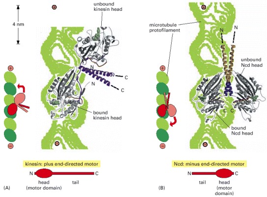
These images were generated by fitting the structures of the free motor-protein dimers (determined by x-ray crystallography) onto a lower resolution image of the dimers attached to microtubules (determined by cryoelectron microscopy). (A) Conventional kinesin has its motor domain at the protein's N-terminus and moves toward the plus end of the microtubule. When one head of the dimer is bound to the microtubule in a post-stroke state (with ATP in the nucleotide binding site), the second, unbound head is pointing toward the microtubule plus end, poised to take the next step. (B) Ncd, a minus-end-directed motor with the motor domain at the C-terminus, forms dimers with the opposite orientation. (From E. Sablin et al., Nature 395:813–816, 1998. © Macmillan Magazines Ltd.)
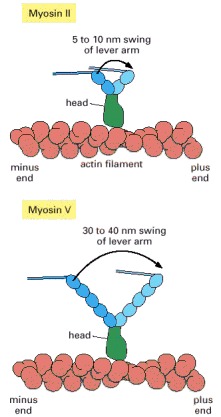
The lever arm of myosin II is much shorter than the lever arm of myosin V. The power stroke in the head swings their lever arms through the same angle, so myosin V is able to take a bigger step than myosin II.
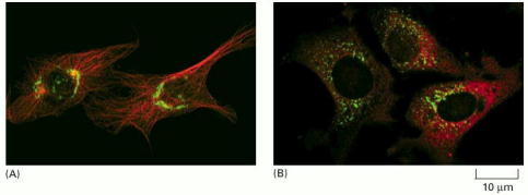
(A) In this endothelial cell, the microtubules are labeled in red, and the Golgi apparatus is labeled in green (using an antibody against a Golgi protein). As long as the system of microtubules remains intact, the Golgi is localized near the centrosome, close to the nucleus at the center of the cell. The cell on the right is in interphase, with a single centrosome. The cell on the left is in prophase, and the duplicated centrosomes have moved to opposite sides of the nucleus. (B) After exposure to nocodazole, which causes microtubules to depolymerize (see Table 16-2), the Golgi apparatus fragments and is dispersed throughout the cell cytoplasm. (Courtesy of David Shima.)
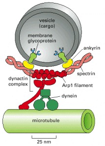
Dynein requires the presence of a large number of accessory proteins to associate with membrane-enclosed organelles. Dynactin is a large complex (red) that includes components that bind weakly to microtubules, components that bind to dynein itself, and components that form a small actinlike filament made of the actin-related protein Arp1. It is thought that the Arp1 filament may mediate attachment of this large complex to membrane-enclosed organelles through a network of spectrin and ankyrin, similar to the membrane-associated cytoskeleton of the red blood cell (see Figure 10-31).
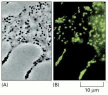
(A) Phase-contrast image of a portion of a melanocyte isolated from a mouse. The black spots are melanosomes, which are membrane-enclosed organelles filled with the skin pigment melanin. (B) The same cell labeled with a fluorescent antibody against myosin V. Every melanosome is associated with a large number of copies of this motor protein. (From X. Wu et al., J. Cell Sci. 110:847–859, 1997. © The Company of Biologists.)
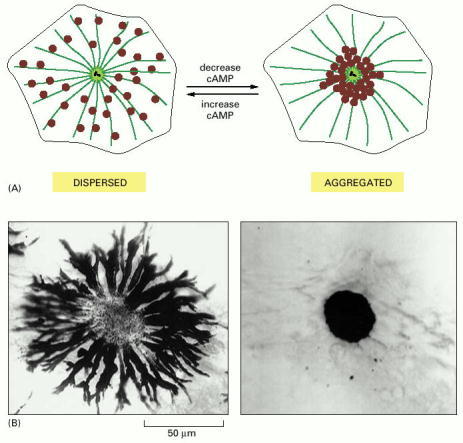
These giant cells, which are responsible for changes in skin coloration in several species of fish, contain large pigment granules, or melanosomes (brown). The melanosomes can change their location in the cell in response to a hormonal or neuronal stimulus. (A) Schematic view of a pigment cell, showing the dispersal and aggregation of melanosomes in response to an increase or decrease in intracellular cyclic AMP (cAMP), respectively. Both redistributions of melanosomes occur along microtubules. (B) Bright-field images of a single cell in a scale of an African cichlid fish, showing its melanosomes either dispersed throughout the cytoplasm (left) or aggregated in the center of the cell (right). (B, courtesy of Leah Haimo.)
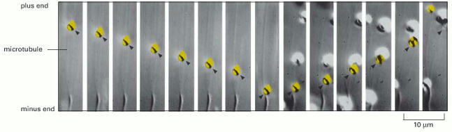
An isolated melanosome (yellow) moves along a microtubule on a glass slide, from the plus end toward the minus end. Halfway through the video sequence, it abruptly switches direction and moves from the minus end toward the plus end. (From S.L. Rogers et al., Proc. Natl. Acad. Sci. USA 94:3720–3725, 1997. © National Academy of Sciences.)
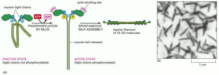
(A) The controlled phosphorylation by the enzyme myosin light-chain kinase (MLCK) of one of the two light chains (the so-called regulatory light chain, shown in light blue) on nonmuscle myosin II in a test tube has at least two effects: it causes a change in the conformation of the myosin head, exposing its actin-binding site, and it releases the myosin tail from a “sticky patch” on the myosin head, thereby allowing the myosin molecules to assemble into short, bipolar, thick filaments. (B) Electron micrograph of negatively stained short filaments of myosin II that have been induced to assemble in a test tube by phosphorylation of their light chains. These myosin II filaments are much smaller than those found in skeletal muscle cells (see Figure 16-52). (B, courtesy of John Kendrick-Jones.)
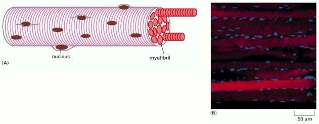
(A) These huge multinucleated cells form by the fusion of many muscle cell precursors, called myoblasts. In an adult human, a muscle cell is typically 50 μm in diameter and can be up to several centimeters long. (B) Fluorescence micrograph of rat muscle, showing the peripherally located nuclei (blue) in these giant cells. (B, courtesy of Nancy L. Kedersha.)
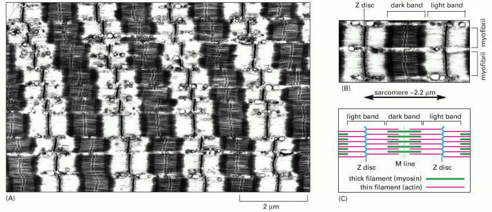
(A) Low-magnification electron micrograph of a longitudinal section through a skeletal muscle cell of a rabbit, showing the regular pattern of cross-striations. The cell contains many myofibrils aligned in parallel (see Figure 16-68). (B) Detail of the skeletal muscle shown in (A), showing portions of two adjacent myofibrils and the definition of a sarcomere. (C) Schematic diagram of a single sarcomere, showing the origin of the dark and light bands seen in the electron micrographs. The Z discs, at each end of the sarcomere, are attachment sites for the plus ends of actin filaments (thin filaments); the M line, or midline, is the location of proteins that link adjacent myosin II filaments (thick filaments) to one another. The dark bands, which mark the location of the thick filaments, are sometimes called A bands because they appear anisotropic in polarized light (that is, their refractive index changes with the plane of polarization). The light bands, which contain only thin filaments and therefore have a lower density of protein, are relatively isotropic in polarized light and are sometimes called I bands. (A and B, courtesy of Roger Craig.)
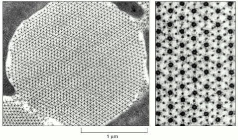
The myosin and actin filaments are packed together with almost crystalline regularity. Unlike their vertebrate counterparts, these myosin filaments have a hollow center, as seen in the enlargement on the right. The geometry of the hexagonal lattice is slightly different in vertebrate muscle. (From J. Auber, J. de Microsc. 8:197–232, 1969.)
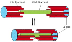
The actin (red) and myosin (green) filaments in a sarcomere slide past one another without shortening.
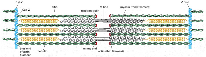
Each giant titin molecule extends from the Z disc to the M line—a distance of over 1 μm. Part of each titin molecule is closely associated with a myosin thick filament (which switches polarity at the M line); the rest of the titin molecule is elastic and changes length as the sarcomere contracts and relaxes. Each nebulin molecule is exactly the length of a thin filament. The actin filaments are also coated with tropomyosin and troponin (not shown; see Figure 16-74) and are capped at both ends. Tropomodulin caps the minus end of the actin filaments, and CapZ anchors the plus end at the Z disc, which also contains α-actinin.
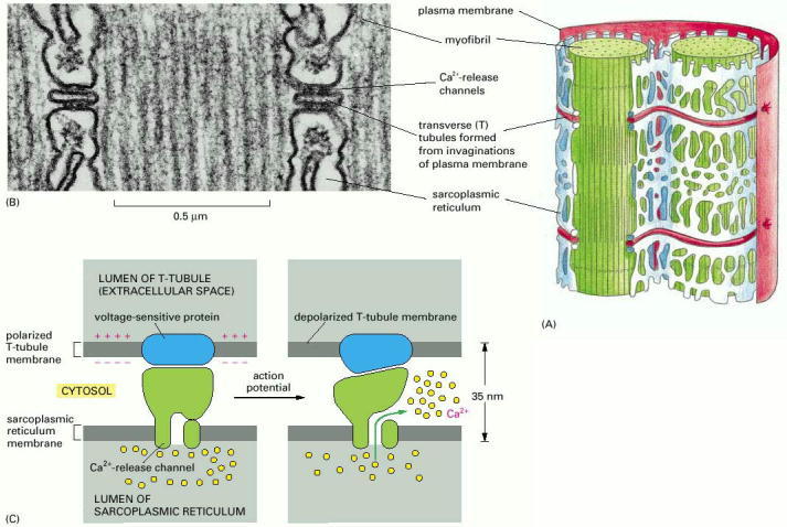
(A) Drawing of the two membrane systems that relay the signal to contract from the muscle cell plasma membrane to all of the myofibrils in the cell. (B) Electron micrograph showing two T tubules. Note the position of the large Ca2+-release channels in the sarcoplasmic reticulum membrane; they look like square-shaped “feet” that connect to the adjacent T-tubule membrane. (C) Schematic diagram showing how a Ca2+-release channel in the sarcoplasmic reticulum membrane is thought to be opened by a voltage-sensitive transmembrane protein in the adjacent T-tubule membrane. (B, courtesy of Clara Franzini-Armstrong.)
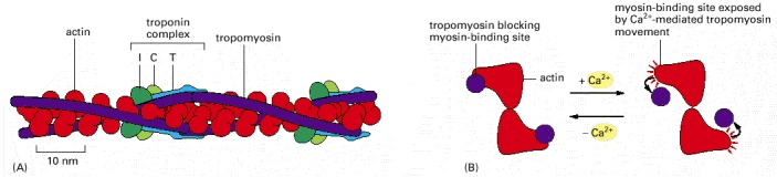
(A) A skeletal muscle cell thin filament, showing the positions of tropomyosin and troponin along the actin filament. Each tropomyosin molecule has seven evenly spaced regions with similar amino acid sequences, each of which is thought to bind to an actin subunit in the filament. (B) A thin filament shown end-on, illustrating how Ca2+ (binding to troponin) is thought to relieve the tropomyosin blockage of the interaction between actin and the myosin head. (A, adapted from G.N. Phillips, J.P. Fillers and C. Cohen, J. Mol. Biol. 192:111–131, 1986. © Academic Press.)
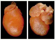
Left, normal heart from a 6-day old mouse pup. Right, heart from a pup with a point mutation in both copies of its cardiac myosin gene, changing Arg 403 to Gln. Both atria are greatly enlarged (hypertrophic), and the mice die within a few weeks of birth. (From D. Fatkin et al., J. Clin. Invest. 103:147, 1999.)
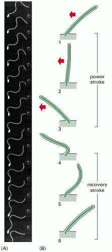
(A) The wave-like motion of the flagellum of a sperm cell from a tunicate. The cell was photographed with stroboscopic illumination at 400 flashes per second. Note that waves of constant amplitude move continuously from the base to the tip of the flagellum. (B) The beat of a cilium, which resembles the breast stroke in swimming. A fast power stroke (red arrows), in which fluid is driven over the surface of the cell, is followed by a slow recovery stroke. Each cycle typically requires 0.1–0.2 sec and generates a force perpendicular to the axis of the axoneme. (A, courtesy of C.J. Brokaw.)
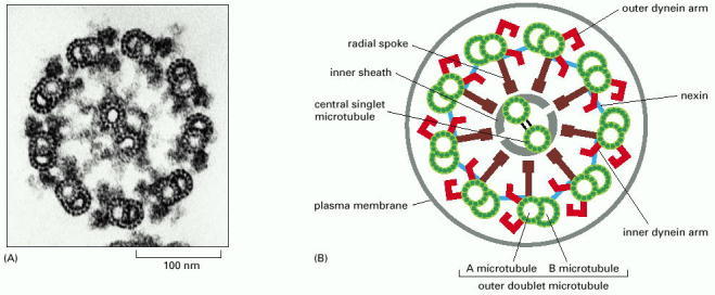
(A) Electron micrograph of the flagellum of a green-alga cell (Chlamydomonas) shown in cross section, illustrating the distinctive “9 + 2” arrangement of microtubules. (B) Diagram of the parts of a flagellum or cilium. The various projections from the microtubules link the microtubules together and occur at regular intervals along the length of the axoneme. (A, courtesy of Lewis Tilney.)
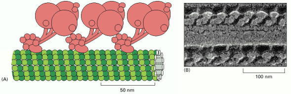
Ciliary (axonemal) dynein is a large protein assembly (nearly 2 million daltons) composed of 9–12 polypeptide chains, the largest of which is the heavy chain of more than 500,000 daltons. (A) The heavy chains are believed to form the major portion of the globular head and stem domains, and many of the smaller chains are clustered around the base of the stem (see Figure 16-56 for a view of the isolated molecule). The base of the molecule binds tightly to an A microtubule in an ATP-independent manner, while the large globular heads have an ATP-dependent binding site for a B microtubule (see Figure 16-77). When the heads hydrolyze their bound ATP, they move toward the minus end of the B microtubule, thereby producing a sliding force between the adjacent microtubule doublets in a cilium or flagellum. The three-headed form of ciliary dynein, formed from three heavy chains, is illustrated here. (B) Freeze-etch electron micrograph of a cilium showing the dynein arms projecting at regular intervals from the doublet microtubules; only the A microtubule is shown. (B, courtesy of John Heuser.)
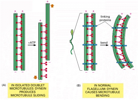
(A) When axonemes are exposed to the proteolytic enzyme trypsin, the linkages holding neighboring doublet microtubules together are broken. In this case, the addition of ATP allows the motor action of the dynein heads to slide one pair of doublet microtubules against the other pair. (B) In an intact axoneme (such as in a sperm), sliding of the doublet microtubules is prevented by flexible protein links. The motor action therefore causes a bending motion, creating waves or beating motions, as seen in Figure 16-76.
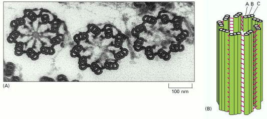
(A) Electron micrograph of a cross section through three basal bodies in the cortex of a protozoan. (B) Diagram of a basal body viewed from the side. Each basal body forms the lower portion of a ciliary axoneme and is composed of nine sets of triplet microtubules, each triplet containing one complete microtubule (the A microtubule) fused to two incomplete microtubules (the B and C microtubules). Other proteins (shown in red in B) form links that hold the cylindrical array of microtubules together. The arrangement of microtubules in a centriole is essentially the same (see Figure 16-24). (A, courtesy of D.T. Woodrow and R.W. Linck.)
Chapter 16.5 - Figures
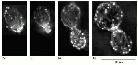
Filamentous actin structures in the yeast cell, labeled here with fluorescent phalloidin, include actin patches (round bright spots) and actin cables (extended lines). (A) In a mother cell, before the formation of the bud, most of the patches are clustered at one end. The cables are lined up and point toward the cluster of patches, which is the site where the bud will emerge. (B) As the small bud grows, most patches remain within it. Cables in the mother cell continue to point toward this site of new cell wall growth. (C) Patches are almost uniformly distributed over the surface of a full-sized bud. Cables in the mother cell remain polarized. (D) Immediately after cell division, mother and daughter cells form new patches, which are concentrated near the division site, although both cells have randomly oriented cables. (From T.S. Karpova et al., J. Cell Biol. 142:1501–1517, 1998. © The Rockefeller University Press.)
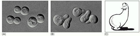
(A) Cells of Saccharomyces cerevisiae are usually spherical. (B) They become polarized when treated with mating factor from cells of the opposite mating type. The polarized cells are called “shmoos.” (C) Al Capp's famous cartoon character, the original Shmoo. (A and B, courtesy of Michael Snyder; C, © 1948 Capp Enterprises, Inc., all rights reserved.)
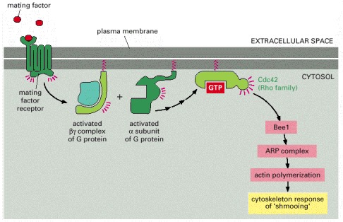
The extracellular mating factor binds to a G-protein-linked receptor in the plasma membrane. Activation of the receptor triggers dissociation of the GTP-bound Gα subunit from a heterotrimeric G-protein (discussed in Chapter 15). This in turn activates the Rho family GTP-binding protein, Cdc42, the yeast homolog of the mammalian small GTPase whose activation triggers the formation of filopodia (see Figure 16-50D). As in mammalian cells, Cdc42 activates a protein (Bee1, the homolog of WASp) that activates the ARP complex, leading to local actin nucleation at the site of mating factor binding. The local actin nucleation and filament growth lead to polarized growth and acquisition of a shmoo shape. In addition, receptor activation triggers other responses through a MAP kinase cascade (discussed in Chapter 15), preparing the haploid cell for mating (not shown).
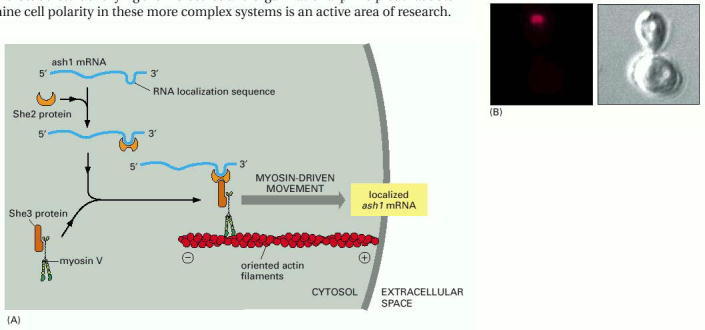
(A) The molecular mechanism of ash1 mRNA localization, as determined by genetics and biochemistry. (B) Fluorescent in situ hybridization (FISH) was used to localize the ash1 mRNA (red) in this dividing yeast cell. The mRNA is confined to the far tip of the daughter cell (here, still a large bud). Ash1 protein, transcribed from this localized mRNA, is also confined to the daughter cell. (B, courtesy of Peter Takizawa and Ron Vale.)
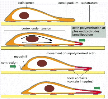
The actin-polymerization-dependent protrusion and firm attachment of a lamellipodium at the leading edge of the cell moves the edge forward (green arrows at front) and stretches the actin cortex. Contraction at the rear of the cell propels the body of the cell forward (green arrow at back) to relax some of the tension (traction). New focal contacts are made at the front, and old ones are disassembled at the back as the cell crawls forward. The same cycle can be repeated, moving the cell forward in a stepwise fashion. Alternatively, all steps can be tightly coordinated, moving the cell forward smoothly. The newly polymerized cortical actin is shown in red.
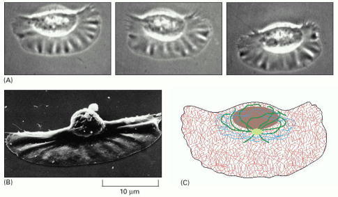
(A) Light micrographs of a keratocyte in culture, taken about 15 sec apart. This cell is moving at about 15 μm/sec. (B) Keratocyte seen by scanning electron microscopy, showing its broad, flat lamellipodium and small cell body, including the nucleus, carried up above the substratum at the rear. (C) Distribution of cytoskeletal filaments in this cell. Actin filaments (red) fill the large lamellipodium and are responsible for the cell's rapid movement. Microtubules (green) and intermediate filaments (blue) are restricted to the regions close to the nucleus. (A and B, courtesy of Juliet Lee.)
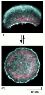
Fragments of the large lamellipodium of a keratocyte can be separated from the main cell, either by surgery with a micropipette or by treating the cell with certain drugs. (A) Many of these fragments continue to move rapidly, with the same overall cytoskeletal organization as the intact keratocytes. Actin (blue) forms a protrusive meshwork at the front of the fragment. Myosin II (pink) is gathered into a band at the rear. This cell fragment was moving toward the top of the photo at the time that it was fixed and stained. (B) Some of the fragments stop moving and assume a symmetric, circular shape. Actin (blue) is distributed uniformly around the circumference, and myosin (pink) is found in spots throughout the cytoplasm. These circular fragments are trying to protrude uniformly in all directions and are therefore paralyzed. Only by coordinating protrusion at the front with contraction at the rear can steady movement be maintained. (From A. Verkovsky et al., Curr. Biol. 9:11–20, 1999. © Elsevier.)
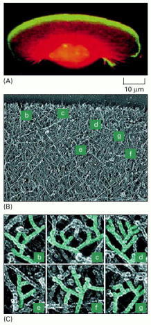
(A) A keratocyte with actin filaments labeled in red by fluorescent phalloidin, and the ARP complex labeled in green with an antibody raised against one of its component proteins. The regions where the two overlap appear yellow. The ARP complex is highly concentrated near the front of the lamellipodium, where actin nucleation is most active. (B) Electron micrograph of a platinum-shadowed replica of the leading edge of a keratocyte, showing the dense actin filament meshwork. The labels denote areas enlarged in C. (C) Closeup views of the marked regions of the actin web at the leading edge shown in B. Numerous branched filaments can be seen, with the characteristic 70° angle formed when the ARP complex nucleates a new actin filament off the side of a preexisting filament (see Figure 16-29). (From T. Svitkina and G. Borisy, J. Cell Biol. 145:1009–1026, 1999. © The Rockefeller University Press.)
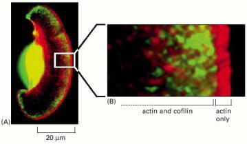
(A) A keratocyte with actin filaments labeled in red by fluorescent phalloidin and cofilin labeled in green with a fluorescent antibody. The regions where the two overlap appear yellow. Although the dense actin meshwork reaches all the way through the lamellipodium, cofilin is not found at the very leading edge. (B) Closeup view of the region marked with the white rectangle in A. The actin filaments closest to the leading edge, which are also the ones that have formed most recently and that are most likely to contain ATP actin (rather than ADP actin) in the filament lattice are generally not associated with cofilin. (From T. Svitkina and G. Borisy, J. Cell Biol. 145:1009–1026, 1999. © The Rockefeller University Press.)
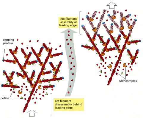
Two time points during advance of the lamellipodium are illustrated, with newly assembled structures at the later time point shown in a lighter color. Nucleation is mediated by the ARP complex at the front. Newly nucleated actin filaments are attached to the sides of preexisting filaments, primarily at a 70° angle. Filaments elongate, pushing the plasma membrane forward because of some sort of anchorage of the array behind. At a steady rate, actin filament plus ends become capped. After newly polymerized actin subunits hydrolyze their bound ATP in the filament lattice, the filaments become susceptible to depolymerization by cofilin. This cycle causes a spatial separation between net filament assembly at the front and net filament disassembly at the rear, so that the actin filament network as a whole can move forward, even though the individual filaments within it remain stationary with respect to the substratum.
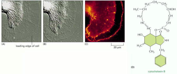
(A) A growth cone from a neuron of the sea slug Aplysia is cultured on a highly adhesive substratum and viewed by differential-interference-contrast microscopy. Microtubules and membrane-enclosed organelles are confined to the bright, rear area of the growth cone (to the left), while a meshwork of actin filaments fills the lamellipodium (on the right). (B) After brief treatment with the drug cytochalasin, which caps the plus ends of actin filaments (see Table 16-2), the actin meshwork has detached from the front edge of the lamellipodium and has been pulled backward. (C) At the time point shown in B, the cell was fixed and labeled with fluorescent phalloidin to show the distribution of the actin filaments. Some actin filaments persist at the leading edge, but the region behind the leading edge is devoid of filaments. Note the sharp boundary of the rearward-moving actin meshwork. (D) The complex cyclic structure of cytochalasin B. (A, B, and C courtesy of Paul Forscher.)
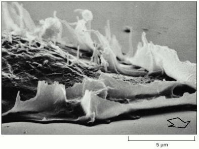
The arrow in this scanning electron micrograph shows the direction of cell movement. As the cell moves forward, lamellipodia that fail to attach to the substratum are swept backward over the dorsal surface of the cell, a movement known as ruffling. (Courtesy of Julian Heath.)
This cell was crawling toward the upper right at the time that it was fixed and labeled with antibodies specific for two myosin isoforms. Myosin I (green) is mainly restricted to the leading edge of pseudopodia at the front of the cell. Myosin II (red) is highest in the posterior, actin-rich cortex. Contraction of the cortex at the posterior of the cell by myosin II may help to push the cell body forward. (Courtesy of Yoshio Fukui.)
These fibroblasts have been cultured on a very thin sheet of silicon rubber. Attachment of the cells, followed by contraction of their cytoskeleton, has caused the rubber substratum to wrinkle. (From A.K. Harris, P. Wild, and D. Stopak, Science 208:177–179, 1980. © AAAS.)
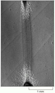
This micrograph shows a region between two pieces of embryonic chick heart (tissue explants rich in fibroblasts and heart muscle cells) that were grown in culture on a collagen gel for 4 days. A dense tract of aligned collagen fibers has formed between the two explants, apparently as a result of fibroblasts tugging on the collagen. (From D. Stopak and A.K. Harris, Dev. Biol. 90:383–398, 1982. © Academic Press.)
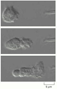
The pipette tip at the right is leaking a small amount of the peptide formyl-Met-Leu-Phe. Only bacterial proteins have formylated methionine residues, so the human neutrophil recognizes this peptide as the product of a foreign invader (discussed in Chapter 25). The neutrophil quickly extends a new lamellipodium toward the source of the chemoattractant peptide (top). It then extends this lamellipodium and polarizes its cytoskeleton so that contractile myosin II is located primarily at the rear, opposite the position of the lamellipodium (middle). Finally, the cell crawls toward the source of this peptide (bottom). If a real bacterium were the source of the peptide, rather than an investigator's pipette, the neutrophil would engulf the bacterium and destroy it. (From O.D. Weiner et al., Nature Cell Biol. 1:75–81, 1999. © Macmillan Magazines Ltd.)
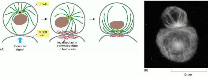
(A) Changes in the cytoskeleton of a cytotoxic T cell after it has made contact with a target cell. The initial recognition event results in signals that cause actin polymerization in both cells at the site of contact. In the T cell, interactions between the actin-rich contact zone and microtubules emanating from the centrosome result in reorientation of the centrosome, so that the associated Golgi apparatus is directly apposed to the target cell. (B) Immuno-fluorescence micrograph in which both the T cell (top) and its target cell (bottom) have been stained with an antibody against microtubules. The centrosome and the microtubules radiating from it in the T cell are oriented toward the point of cell-cell contact. In contrast, the microtubule array in the target cell is not polarized. (B, from B. Geiger, D. Rosen and G. Berke, J. Cell Biol. 95:137–143, 1982. © The Rockefeller University Press.)
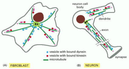
(A) In a fibroblast, microtubules emanate outward from the centrosome in the middle of the cell. Vesicles with plus-end-directed kinesin attached move outward, and vesicles with minus-end-directed dynein attached move inward. (B) In a neuron, microtubule organization is more complex. In the axon, all microtubules share the same polarity, with the plus ends pointing outward toward the axon terminus. No one microtubule stretches the entire length of the axon; instead, short overlapping segments of parallel microtubules make the tracks for fast axonal transport. In dendrites, the microtubules are of mixed polarity, with some plus ends pointing outward and some pointing inward.
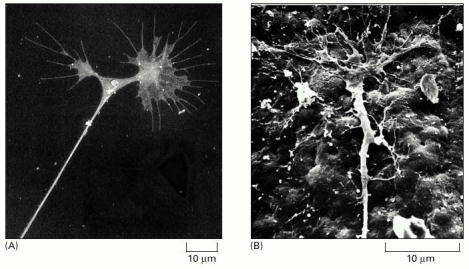
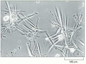
(A) Scanning electron micrograph of two growth cones at the end of a neurite, put out by a chick sympathetic neuron in culture. Here, a previously single growth cone has recently split into two. Note the many filopodia and the large lamellipodia. The taut appearance of the neurite is due to tension generated by the forward movement of the growth cones, which are often the only firm points of attachment of the axon to the substratum. (B) Scanning electron micrograph of the growth cone of a sensory neuron crawling over the inner surface of the epidermis of a Xenopus tadpole. (A, from D. Bray, in Cell Behaviour [R. Bellairs, A. Curtis, and G. Dunn, eds.]. Cambridge, UK: Cambridge University Press, 1982; B, from A. Roberts, Brain Res. 118:526–530, 1976. © Elsevier.)
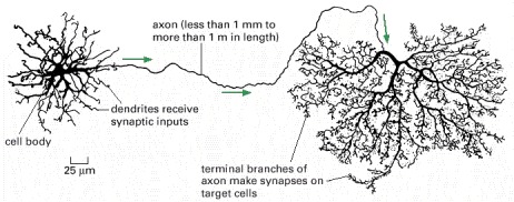
The neuron shown is from the retina of a monkey. The arrows indicate the direction of travel of the electrical signal along the axon. The longest and largest neurons in the human body extend for a distance of about 1 m (1 million μm), from the base of the spinal cord to the tip of the big toe, and have an axon diameter of 15 μm. (Adapted from B.B. Boycott, in Essays on the Nervous System [R. Bellairs and E.G. Gray, eds.]. Oxford, UK: Clarendon Press, 1974.)